In this post, we’ll go through various tests that we can perform to determine whether a diode is functioning properly or not, all while employing a digital multimeter’s features.
We can do a variety of tests to see if a diode is operating as it should. We will use and take advantage of the traits and behaviors that a good diode should exhibit in order to assess if it is excellent or defective.
So let’s start:

How to Test a Diode Using a Multimeter’s Ohmmeter
Checking a diode with your multimeter set to the ohmmeter setting is a very effective test you can do.
We may perform this quick test to see if it is good, open, or shorted.
Hence, we grab the ohmmeter and set it across the diode’s leads. It’s crucial to consider your orientation.
Test for Anode-Cathode Diode Resistance
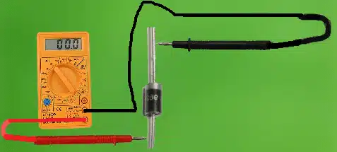
Then, we take the ohmmeter and set it up as shown above, with the positive probe on the anode of the diode (the black portion) and the negative probe on the cathode of the diode (the silver strip). With this configuration, the resistance reading on the diode should be in the low tens of thousands or hundreds of thousands of ohms range. For instance, you might read 230K.
Test for Cathode-Anode Diode Resistance
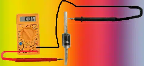
So that the positive probe of the multimeter is now on the cathode of the diode and the negative lead is now on the anode, grab the ohmmeter now and switch the probes around. The diode should now read a significantly higher resistance, exceeding 1M, in this configuration. Given the large resistance, it might even represent an open circuit, or “OL” for an open loop.
The diode is in good condition if you read a reasonably low resistance with the leads attached one way and a high resistance with the leads attached the other way. The resistance readings on a diode should be quite high in the reverse-biased direction and comparatively low in the forward-biased direction.
Active Diode
High resistance readings from the diode in both directions indicate that the diode is open. A diode shouldn’t register extremely high resistance when biased forward. The circuit’s diode has to be replaced.
Diode Shorted
The diode is shorted if it displays low resistance readings in both directions. A diode shouldn’t measure low resistance when biased the other way. The circuit’s diode has to be replaced.
How to Use a Multimeter’s Voltmeter to Test a Diode
Use a multimeter’s voltmeter as a second test to determine whether a diode is present (or simply a voltmeter if you have one).
We may use these characteristics to determine whether a diode is reading a healthy and accurate voltage across its terminals since diodes drop a certain voltage across their terminals when their threshold voltage is surpassed.
We must connect the diode to a circuit that supplies it with DC voltage in order to do this test.
A useful test to examine a diode is the circuit below:
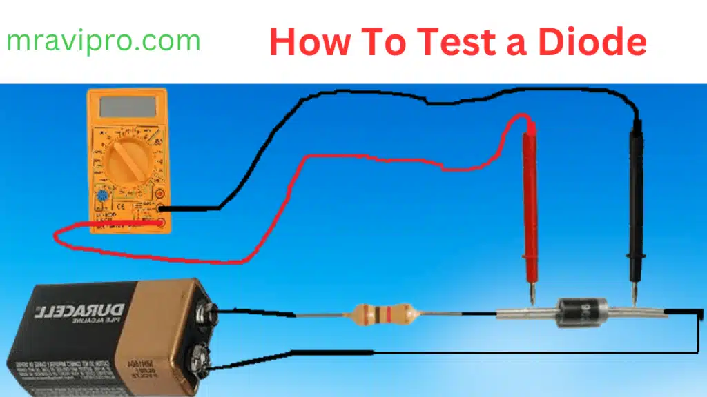
Over the threshold voltage, you can apply any voltage to the diode. The diode will then reduce the voltage between its terminals to the threshold level.
Very likely, you are using a silicon diode as a diode. The voltage loss across the terminals of silicon diodes is roughly 0.6–0.7 volts. So, this range of voltage should be read while measuring the voltage across the diode leads. If you succeed, the diode is reading a sound voltage and ought to be fine. The voltage dropped across the diode, if it is a germanium diode, should be somewhere close to 0.3 volts.
To prevent the diode from overheating when testing it with voltage, be careful to use a resistor. Avoid connecting the electricity straight to the
To avoid causing the diode to overheat, use a resistor when testing the diode with voltage. Never connect the voltage to the diode directly. Put a resistor between them. Any resistor value in that range, such as 1K, will do.
Diode Open
The diode is open and hence defective if you measure an extremely high voltage across it, such as the voltage you are providing it with. It must therefore be replaced.
Diode Shorted
If the voltage across the diode is zero or very low, the diode is shorted and needs to be replaced.
Here are two reliable tests you can use to determine whether a diode is functioning properly.
Also, Read This Article:
How to test a Zener Diode
Solar Thermal Power Plant in India, 2023
Spy camera circuit diagram pdf free download 2023
6S LiPo Battery: Full Details and Problem Solution
How to test a diode on a circuit board
A diode is a component that allows current to flow in one direction but blocks it in the opposite direction. To test a diode on a circuit board, you need a multimeter that can measure resistance. First, disconnect the power supply from the circuit board and remove the diode from its socket. Then, set the multimeter to the lowest resistance range and connect the probes to the diode terminals. It doesn’t matter how the probes are polarized. If the multimeter shows a low resistance value, it means the diode is conducting in the forward direction. Next, reverse the probes and measure again. If the multimeter shows a high resistance value, it means the diode is blocking in the reverse direction. A good diode should have low resistance in one direction and high resistance in the other direction. If the multimeter shows low or high resistance in both directions, it means the diode is either shorted or open and needs to be replaced.
How to test a diode with an ohmmeter
A diode is a device that allows current to flow in one direction but blocks it in the opposite direction. To test a diode with an ohmmeter, you need to do the following steps:
Choose the lowest resistance setting on the ohmmeter.
Determine the diode’s anode and cathode terminals.
The anode is usually marked with a stripe or a ring on the body of the diode. The cathode and the anode should be connected to the positive and negative leads of the ohmmeter, respectively.
Note the reading on the meter. It should show a low resistance value, indicating that the diode is conducting in the forward direction.
Reverse the leads of the ohmmeter and connect them to the opposite terminals of the diode. Note the reading on the meter. It should show a high resistance value, indicating that the diode is blocking current in the reverse direction.
If the meter shows a low resistance value in both directions or a high resistance value in both directions, the diode is defective and needs to be replaced.
How to test a diode using an analog multimeter
To test a diode using an analog multimeter, follow these steps:
Set the multimeter to the lowest resistance range (ohms).
Determine the diode’s anode and cathode terminals.
The anode is usually marked with a stripe or a ring on the body of the diode. Connect the positive (red) probe of the multimeter to the anode and the negative (black) probe to the cathode.
Note the reading on the multimeter. It should show a low resistance value, indicating that the diode is conducting current in the forward direction.
Reverse the probes and connect them to the opposite terminals of the diode.
Note the reading on the multimeter. It should show a high resistance value, indicating that the diode is blocking current in the reverse direction.
If the multimeter shows a low resistance value in both directions, the diode is shorted. If it shows a high resistance value in both directions, the diode is open. In either case, the diode is defective and needs to be replaced.
How to test a diode in a parallel circuit
To test a diode in a parallel circuit, you need to disconnect the diode from the circuit and use a multimeter to measure its resistance. A good diode should have a low resistance in one direction and a high resistance in the other direction. If the diode has the same resistance in both directions, it is shorted. If the diode has a very high resistance in both directions, it is open.
How to test diodes in solar panel
To test diodes in a solar panel, you need a multimeter and a screwdriver. First, disconnect the solar panel from the battery and any other devices. Then, remove the junction box cover with the screwdriver and locate the diodes. Next, set the multimeter to the diode test mode and connect the probes to the terminals of each diode. The multimeter should display a low resistance value when the probes are connected in one direction, and a high resistance value when they are reversed. If the multimeter shows no resistance or infinite resistance in both directions, the diode is faulty and needs to be replaced.