The 555 timer IC is a versatile integrated circuit that can be used in a wide range of applications, including connecting a throttle and accelerator. In this article, we will explore the process of connecting a throttle and accelerator with the 555 timer IC, providing you with a step-by-step guide to ensure a successful implementation. Whether you are a hobbyist or an electronics enthusiast, this article will help you understand how to integrate these components effectively.

How does the 555 Timer IC work?
Before we delve into the details of connecting the throttle and accelerator with the 555 IC, let’s briefly understand how the 555 timer IC functions.
The 555 IC is a popular timer integrated circuit that operates in three modes: astable, monostable, and bistable.
In the context of connecting the throttle and accelerator, we will primarily focus on the astable mode.
This mode allows the 555 IC to operate as an oscillator, generating square-wave signals.
By adjusting the timing components of the IC, we can control the frequency and duty cycle of the output signal. 555 timer ic use throttle
Required Components
To connect the throttle and accelerator with the 555 timer IC, you will need the following components:
- 555 IC
- Throttle sensor
- Accelerator pedal
- Resistors
- Capacitors
- Transistors
- Diodes
- Breadboard
- Connecting wires

- ICNE555 IC
- transistorbc548
- 1k
- 10 ohm
- 4.7k
- ceramic capacitor 104 uf
- 0.1uf
- Zener diode,6 voltst
- throttle
Step-by-Step Manual for Connecting Throttle and Accelerator With 555 Timer IC
Gather the Required Components
Before starting the connection process, ensure that you have gathered all the necessary components mentioned above.
Having everything ready will make the process smoother.
Study the Throttle and Accelerator Mechanism
To effectively connect the throttle and accelerator with the 555 IC, it’s essential to understand how these components work.
Study the throttle sensor and accelerator pedal mechanism to identify the relevant input and output connections.
Connect the Throttle Sensor
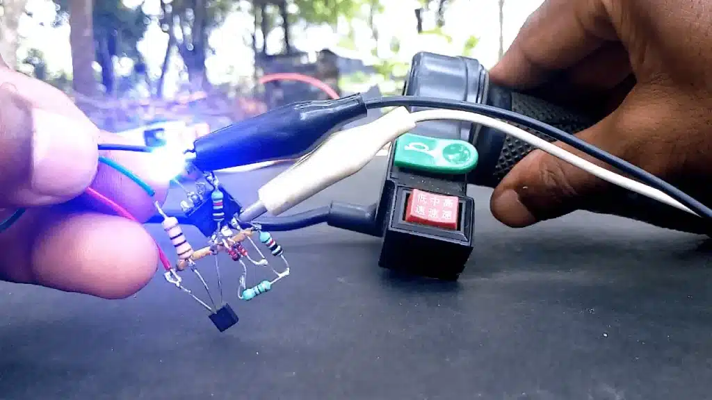
Connect the throttle sensor to the input pin of the 555 IC. The throttle sensor will provide the input signal to the IC, which will be processed to generate the desired output.
Connect the Accelerator Pedal
Connect the accelerator pedal to the output pin of the 555 IC. This connection allows the generated square wave signal to control the accelerator pedal’s movement.
Configure the 555 Timer IC
Configure the 555 IC to operate in the astable mode. Adjust the timing components, such as resistors and capacitors, to control the frequency and duty cycle of the output signal.
Test the Connection
Once the connections are made and the 555 IC is configured, it’s time to test the setup. Gradually vary the input signal from the throttle sensor and observe the corresponding movement of the accelerator pedal.
Fine-tune the Circuit
Based on the test results, you may need to fine-tune the circuit by adjusting the timing components or modifying the connection setup. Experiment with different settings to achieve the desired responsiveness and functionality.
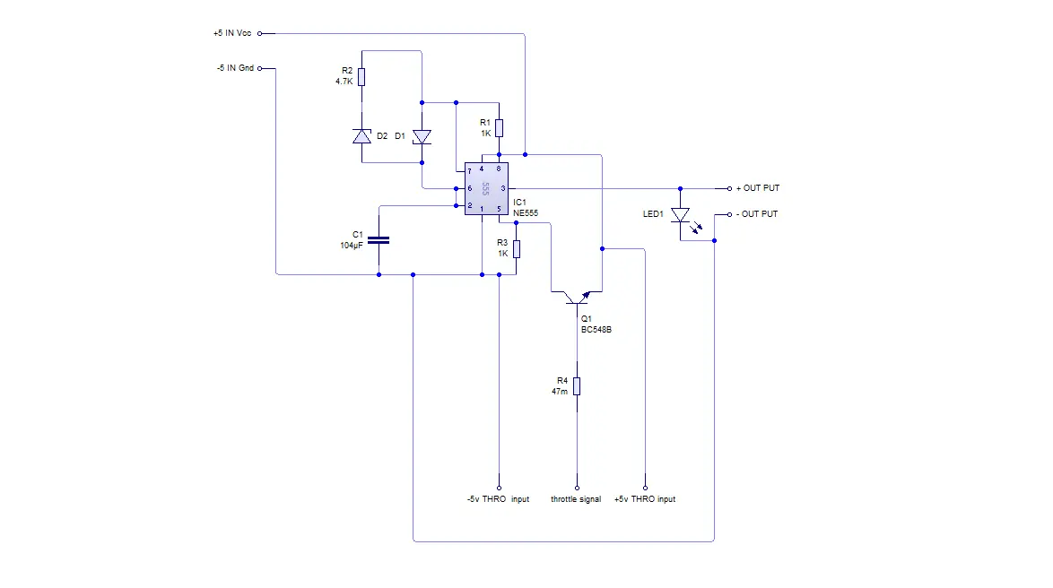
High-Quality Circuit Diagram
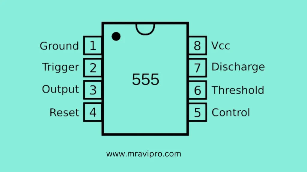
555 timer ic datasheet Download

Conclusion
Connecting a throttle and accelerator with the 555 timer IC allows you to control the movement of the accelerator pedal based on the input from the throttle sensor.
By following the step-by-step guide provided in this article, you can successfully integrate these components and create a functional setup. Remember to adhere to standard safety practices and experiment with different settings to achieve the desired performance.
Now that you have a good understanding of how to connect the throttle and accelerator with the 555 timer IC, it’s time to unleash your creativity and apply this knowledge to your electronic projects.
Also Read This Article:
- How to Make an Electric Bike Speed Controller at Home.
- How to Make a BLDC Motor ESC Using MOSFET
- 5V PWM Signal Booster Convert 12V PWM Signal Generator
- How to Make a BLDC Motor ESC Using MOSFET
- Transparent Phone at Your Home Full Details 2023
FAQ
Can any type of throttle sensor be used with the 555 timer IC?
Yes, the 555 timer IC is compatible with various types of throttle sensors. Ensure that the sensor’s output is within the acceptable voltage range of the IC.
What is the purpose of using a 555 timer IC in this setup?
The 555 timer IC acts as an oscillator, generating square wave signals that control the movement of the accelerator pedal based on input from the throttle sensor.
Can I use a microcontroller instead of the 555 timer IC?
While a microcontroller can be used for this purpose, the 555 timer IC provides a simpler and more straightforward solution for basic applications.
Are there any safety precautions to consider when connecting the throttle and accelerator with the 555 timers IC?
It’s crucial to follow standard electrical safety practices while working with any electronic components. Ensure that the power supply is disconnected during the connection process and take necessary precautions to avoid short circuits.
Can I find pre-built circuits for connecting the throttle and accelerator with the 555 timers IC?
Yes, you may find pre-built circuits or schematics online that can serve as a starting point for your project. However, it’s always beneficial to understand the underlying principles to customize the circuit as per your specific requirements.
Where can I find accessoryresources for learning about the 555 timer IC?
You can refer to reputable electronic websites, such as Wikipedia, for detailed information about the 555 timer IC and its various applications.