What is the NE555 Timer IC?
A flexible and frequently used integrated circuit, the NE555 Timer IC is also known as the NE555 oscillator or NE555 timer. It was first created in 1971 by Signetics, which is now a division of NXP Semiconductors, and has since grown to be one of the most well-liked and durable integrated circuits in the electronics sector.
The NE555 Timer IC was created primarily to produce precise and consistent time delays or oscillations. Its ease of use, dependability, and affordability have made it the preferred option for many applications, including timing, frequency generation, pulse-width modulation, and sequential timing.
Key Features of the NE555 Timer IC
The NE555 Timer IC has a multitude of vital properties that make it extremely versatile and appropriate for a variety of applications. Let’s examine some of its salient characteristics:
Operating Modes
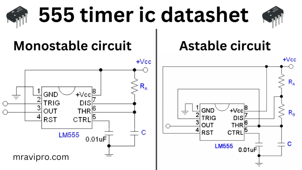
The NE555 Timer IC can operate in three different modes: monostable, astable, and bistable. Each mode has its own characteristics and applications, allowing the IC to adapt to different timing requirements.

Wide Range of Timing Capacities
A wide range of timing capacities can be achieved by adjusting the timing capacitor and resistors used in conjunction with the NE555 Timer IC. With this flexibility, oscillations and time delays can be controlled precisely in terms of length.
Adjustable Duty Cycle
The NE555 Timer IC allows the duty cycle to be changed while operating in astable mode (the ratio of the ON time to the total period). Applications like pulse-width modulation and waveform synthesis benefit greatly from this feature.
High Output Current
Since the NE555 Timer IC has a source or sink current capability of up to 200 mA, it can be used to directly drive a range of loads. In many applications, this functionality removes the need for additional driving circuits.
Wide Supply Voltage Range
The NE555 Timer IC can function in low-voltage and standard-voltage systems and has a supply voltage range of 4.5V to 16V, making it compatible with a variety of electrical equipment.
Applications of the NE555 Timer IC
Because of its adaptability and dependability, the NE555 Timer IC is extensively utilized in a wide range of electrical circuits. Following are a few typical applications for this technology:
Pulse Generation
The NE555 Timer IC is frequently used to produce accurate, steady pulses with a range of durations. Applications for it include pulse-width modulation, time delays, and frequency dividers.
Oscillator Circuits
The NE555 Timer IC can be used as an easy-to-use, low-cost oscillator by setting it up in astable mode. These oscillator circuits are used in timekeeping, tone creation, and clock generation.
Sequential Timing
The NE555 Timer IC can be used to regulate the timing of different stages in applications that call for sequential timing or event sequencing. It is helpful in applications like traffic lights and sequential LED displays because it offers exact control over the length of each stage.
PWM (Pulse-Width Modulation)
The adjustable duty cycle characteristic of the NE555 Timer IC makes it appropriate for producing pulse-width modulation signals. PWM is frequently employed in processes including audio signal creation, LED dimming, and motor speed control.
Timing Circuits
Timer, alarm, and time-delay switch timing circuits frequently employ the NE555 Timer IC. It is a perfect fit for various applications thanks to its accuracy and stability.

Technical Specifications of the NE555 Timer IC
To better understand the capabilities of the NE555 Timer IC, let’s take a look at its technical specifications:
- Supply Voltage: 4.5V to 16V
- Operating Temperature Range: -40°C to +85°C
- Timing Capacitance Range: 100 pF to 1000 µF
- Maximum Output Current: 200 mA
- Threshold Voltage: 1/3 Vcc
- Trigger Voltage: 1/2 Vcc
- Reset Voltage: 0.7V
- Output Voltage Swing: Close to Ground and Vcc
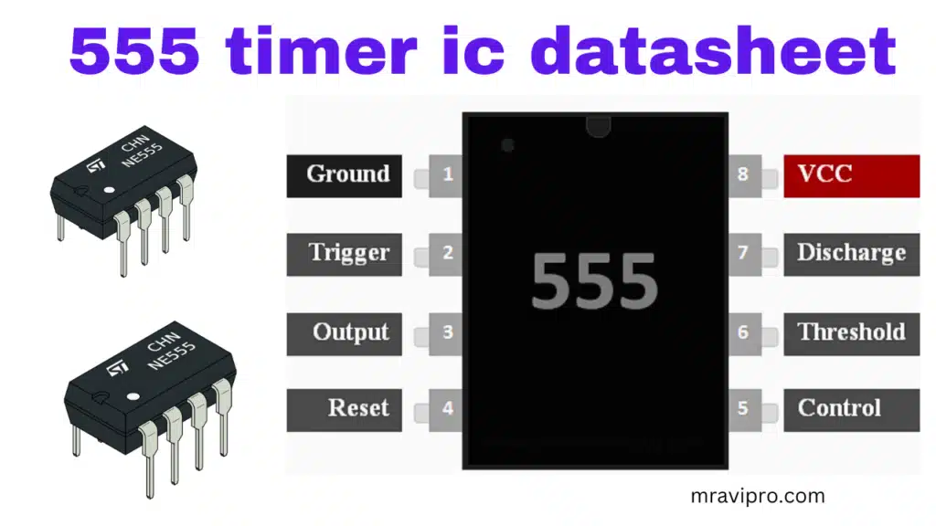
- Pin 1: Ground (GND)
- Pin 2: Trigger (TR)
- Pin 3: Output (OUT)
- Pin 4: Reset (RESET)
- Pin 5: Control Voltage (CV)
- Pin 6: Threshold (TH)
- Pin 7: Discharge (DIS)
- Pin 8: Vcc (Supply Voltage)
Conclusion
The NE555 Timer IC is a flexible and dependable integrated circuit that has a wide range of applications in electrical circuits. It is a favorite of both professionals and enthusiasts in the field of electronics due to its versatility, changeable timing capabilities, and simplicity of use. You can use the NE555 Timer IC to develop unique and useful electronic circuits by comprehending its features, applications, and technical specs.
555 Timer IC Works:
FAQ
What is the pin configuration of the NE555 Timer IC?
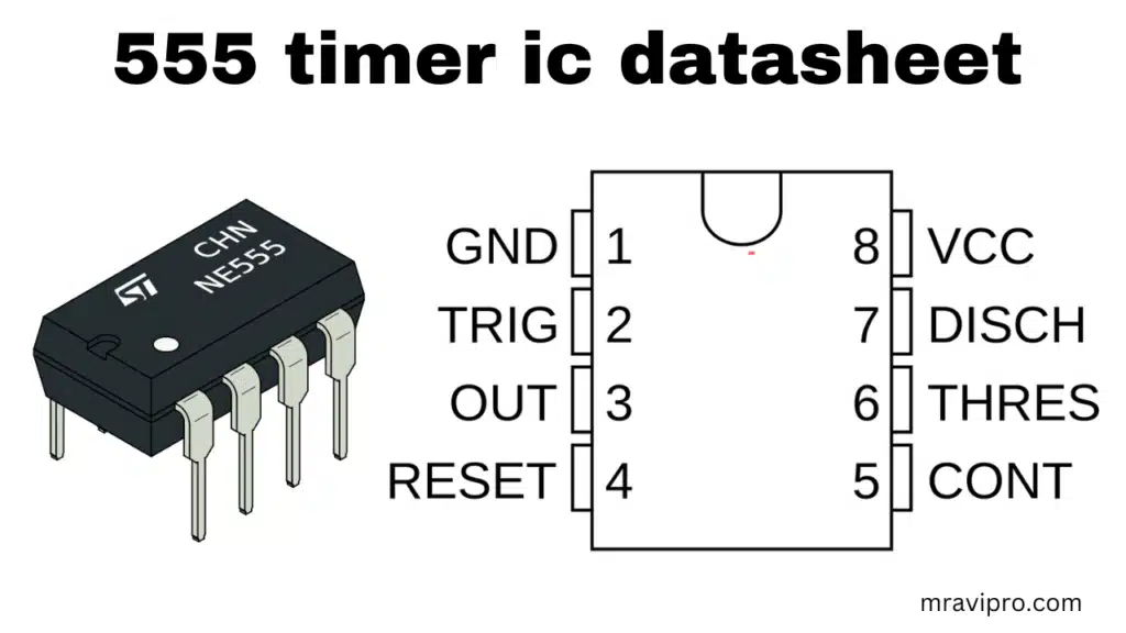
The NE555 Timer IC has eight pins, each serving a specific purpose. Here is the pin configuration:
Pin 1: Ground (GND)
Pin 2: Trigger (TR)
Pin 3: Output (OUT)
Pin 4: Reset (RESET)
Pin 5: Control Voltage (CV)
Pin 6: Threshold (TH)
Pin 7: Discharge (DIS)
Pin 8: Vcc (Supply Voltage)
Can the NE555 Timer IC operate with both positive and negative supply voltages?
No, only positive supply voltages are permitted for the NE555 Timer IC to function. Applications requiring negative supply voltages cannot use it.
How can I calculate the timing components for the NE555 Timer IC?
The timing components, such as the timing capacitor (C) and timing resistors (R1 and R2), can be calculated using the following formulas:
1. Monostable Mode: Time Delay (T) = 1.1 × R1 × C
2. Astable Mode: Frequency (f) = 1.44 / ((R1 + 2 × R2) × C)
Can I use the NE555 Timer IC in high-frequency applications?
Due to its inherent restrictions, the NE555 Timer IC is not appropriate for high-frequency applications. Applications with frequencies up to a few hundred kilohertz frequently employ it.
Are there any alternatives to the NE555 Timer IC?
Yes, there are alternative timer ICs available in the market, such as the TLC555 and LM555. These ICs offer similar functionalities and can be used as replacements for the NE555 Timer IC.
- Also, Read This Article:- 3.7Volt Li-ion Battery Charger Full Details & Solution.
- Also, Read This Article:- How to Make a BLDC Motor ESC Using MOSFET
- Also, Read This Article:– 555 timer ic use throttle or accelerator sensor circuit diagram
- Also, Read This Article:- How to Make a BLDC Motor ESC Using MOSFET
- Also, Read This Article:- 5V PWM Signal Booster Convert 12V PWM Signal Generator
- Also, Read This Article:- How to Make a BLDC Motor ESC Using MOSFET
- Also, Read This Article:- RU6888r Mosfet Datasheet Full Details Download Free