There are two quick, easy tests you can perform to determine whether a Zener diode is in good condition or not. Both tests will be covered in this essay.
Test Zener Diode with Multimeter
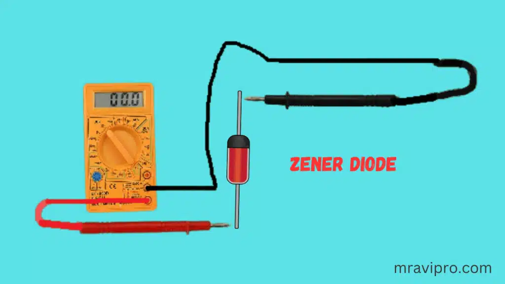
Checking a zener diode with your multimeter set to the ohmmeter setting is a very effective test you can do. We may perform this quick test to see if it is good, open, or shorted.
Hence, we grab the ohmmeter and set it across the diode’s leads. It’s crucial to consider your orientation.
Test for Anode-Cathode Diode Resistance
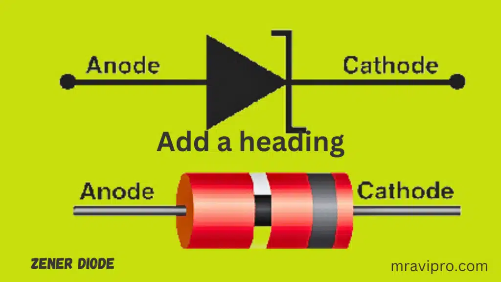
As shown in the illustration above, we first take the ohmmeter and position the positive probe on the anode of the diode (the lead connected to the brown portion of the zener diode) and the negative probe on the cathode of the diode (the lead connected to the side of the Zener diode with the black strip). The diode in this configuration should register a reasonably low resistance, possibly a few hundred thousand ohms. For instance, you might read about 450K.
Test for Cathode-Anode Diode Resistance
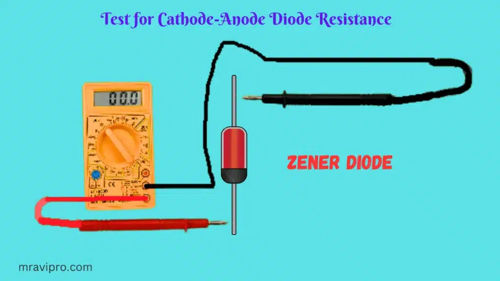
So that the positive probe of the multimeter is now on the cathode of the diode and the negative probe is now on the anode of the diode, grab the ohmmeter now and swap the probes around.
The diode in this configuration should now read a significantly greater resistance, considerably over 1 M. For instance, a common reading might be 2.3 M. Given the high resistance, the multimeter may even display ‘OL’ for an open circuit.
The zener diode is in good working order if you read a reasonably low resistance with the leads facing one way and high resistance with the leads facing the other. When biased forward, a zener diode should show comparatively low resistance, and when biased backward, extremely high resistance.
Diode Open
High resistance readings in both directions on a zener diode indicate that the diode is open. A diode shouldn’t register extremely high resistance when biased forward. The circuit’s diode has to be replaced.
Short Diode
The zener diode is shorted if it displays low resistance readings in both directions. A diode shouldn’t measure low resistance when biased the other way. The circuit’s diode has to be replaced.
How to Use a Multimeter’s Voltmeter to Test a Zener Diode
Using a multimeter’s voltmeter to measure a zener diode’s voltage can allow you to determine whether it is malfunctioning or not (or simply a voltmeter if you have one).
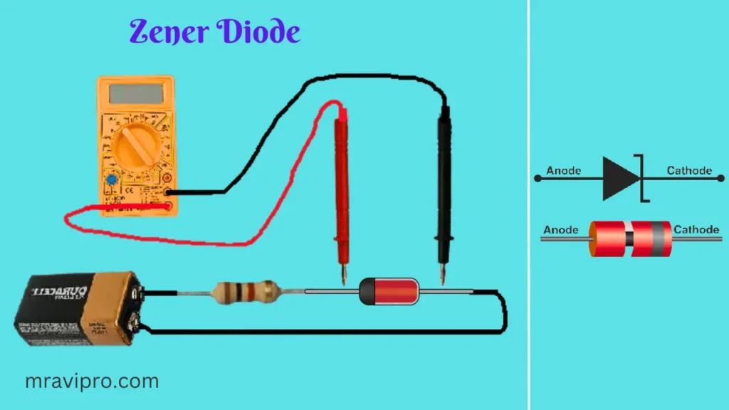
We must give voltage to the zener diode in reverse bias in series with a resistor in order for this test to function. The voltage must be greater than the zener diode’s rated zener voltage. In the circuit below, a 9-volt battery is used to supply power to the Zener diode and a 1K resistor. The supplied 9 volts are well below the 5.1 volts the Zener diode is rated for.
It is necessary to measure a voltage close to the rated zener voltage when measuring the voltage across the zener diode. A zener diode is in good condition if it reads a voltage close to its rated zener voltage, VZ.
Active Diode
The diode is open and hence malfunctioning if it reads a voltage that is significantly higher than, or very close to, the supply voltage feeding it. It has to be changed.
Diminished Diode
The diode is malfunctioning and needs to be replaced if it detects a voltage that is significantly lower than its rated voltage, such as near 0 volts. These are two straightforward but efficient tests for zener diodes.
Also, Read This Article:
How to test a diode
Solar Thermal Power Plant in India, 2023
Spy camera circuit diagram pdf free download 2023
6S LiPo Battery: Full Details and Problem Solution
How to test a Zener diode in the circuit
To test a Zener diode in the circuit, you need a multimeter and a power supply. First, disconnect the diode from the circuit and set the multimeter to measure resistance.
After that, the multimeter’s positive lead goes to the diode’s anode, and its negative lead to its cathode. The resistance should be very high, indicating that the diode is not conducting with reverse bias. Next, reverse the leads and measure the resistance again.
The resistance should be low, indicating that the diode is conducting with a forward bias. Finally, reconnect the diode to the circuit and set the power supply to a voltage higher than the Zener voltage of the diode. Measure the voltage across the diode with the multimeter.
The voltage should be equal to the Zener voltage, indicating that the diode is regulating the voltage in reverse breakdown mode.
Zener diode testing using a multimeter
A Zener diode is a type of diode that allows current to flow in both directions, but only when the voltage across it reaches a certain level, called the Zener voltage. To test a Zener diode using a multimeter, you need to follow these steps:
Set the multimeter to measure resistance and connect the positive lead to the anode (the end with a black stripe) and the negative lead to the cathode of the diode.
Read the resistance value on the multimeter display. It should be very high, indicating that the diode is blocking the current in this direction.
Reverse the leads and connect the positive lead to the cathode and the negative lead to the anode of the diode.
Read the resistance value again. It should be very low, indicating that the diode is allowing the current to flow in this direction.
Set the multimeter to measure voltage and connect it to a power source that can provide a variable voltage, such as a battery with a potentiometer.
Connect the positive lead of the multimeter and the power source to the anode of the diode and the negative lead of both to the cathode of the diode.
Increase the voltage gradually and observe the voltage reading on the multimeter display. It should remain constant until it reaches the Zener voltage, then it should increase rapidly as the diode starts to conduct in reverse.
Note down the Zener voltage value and compare it with the specifications of the diode. It should be close to the rated value; otherwise, the diode may be defective or damaged.
How to identify zener diode
A Zener diode is a special type of diode that can conduct current in both directions when it is reverse-biased above a certain voltage. This voltage is called the zener voltage, and it depends on the doping level of the diode. Zener diodes are often used as voltage regulators or references in circuits.
To identify a Zener diode, you can look for some clues in its appearance or markings, or you can measure its voltage using a multimeter. To achieve that, follow these steps:
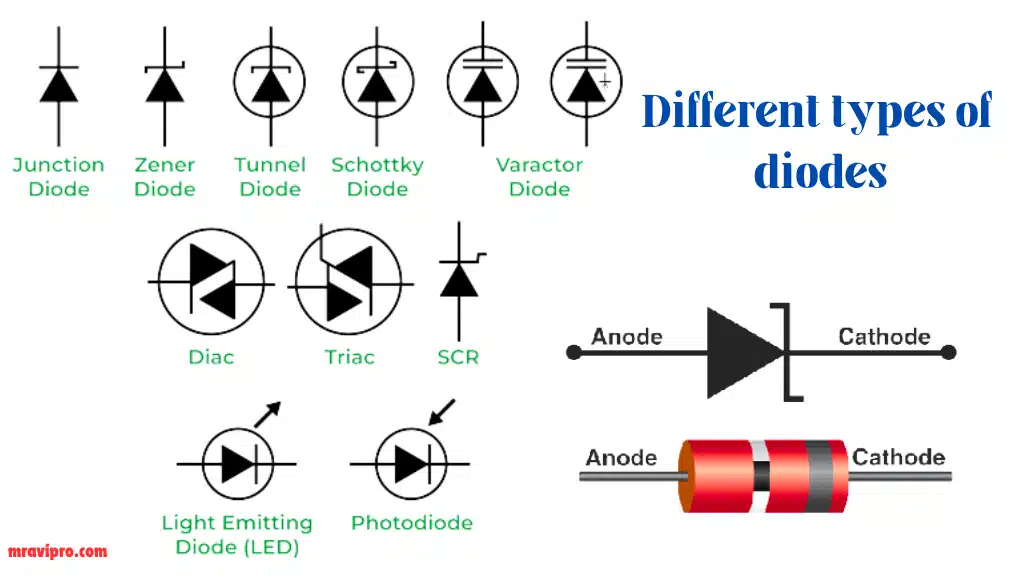
Look for the shape and color of the diode. Zener diodes may have a dark plastic or metal casing with a stripe on one end, indicating the cathode. They may also have a glass casing with a white, black, or blue stripe, or a copper-colored casing. The stripe is always on the cathode side.
Look for the number or code on the diode. Zener diodes usually have a number starting with 1N followed by four digits, such as 1N4734A or 1N751. This number indicates the zener voltage and other specifications of the diode. You can search for this number online to find more information about the diode.
Measure the forward-biased voltage of the diode using a multimeter. Set the multimeter to diode mode and connect the positive (red) lead to the anode (unmarked) side and the negative (black) lead to the cathode (striped) side of the diode. The multimeter should display a reading of about 0.5 to 0.7 volts, which is typical for silicon diodes.
Measure the reverse-biased voltage of the diode using a multimeter. Switch the leads of the multimeter and connect them to the opposite sides of the diode.
The multimeter should display an overload or no reading, indicating no current flow, until you reach the zener voltage. Then, the multimeter should display a reading close to the zener voltage, indicating that the diode is conducting in reverse. For example, if you have a 5.1V zener diode, you should see a reading of about 5.1V when you apply more than 5.1V in reverse.,
How to check the zener diode value
A Zener diode is a type of diode that can regulate the voltage across it. To check the Zener diode value, you need a multimeter and a power supply. Here are the steps to follow:
Set the multimeter to measure resistance and connect it to the diode in both directions. The diode should show low resistance in one direction and high resistance in the other. If not, the diode is damaged or defective.
Set the power supply to a voltage higher than the expected zener voltage and connect it to the diode in reverse bias. The diode should start conducting current when the voltage reaches the zener voltage.
Measure the voltage across the diode with the multimeter. This is the zener diode value. It should be close to the rated value of the diode.
How to measure zener diode resistance
A Zener diode is a type of diode that allows current to flow in both directions but has a different voltage drop in each direction. The voltage drop in the reverse direction is called the zener voltage, and it is a characteristic of the diode.
To measure the zener diode resistance, we need to apply a voltage across the diode that is higher than the zener voltage and measure the current that flows through it.
The resistance is then calculated by dividing the voltage by the current, using Ohm’s law. The resistance of a zener diode is not constant but varies with the applied voltage and temperature.
What is another name for a Zener?
A Zener diode is a type of diode that allows current to flow in both directions when it reaches a certain voltage level, called the Zener voltage. This makes it useful for regulating voltage in circuits. Another name for a Zener is a breakdown diode because it operates in the reverse breakdown region of the diode characteristic curve.