Hi friends, how are you all? Today, I will show you how to make a high-speed BLDC fan using a CPU fan. If you want to make one, then read my entire post, and you will be able to make a high-speed wedding fan. Let’s get started.
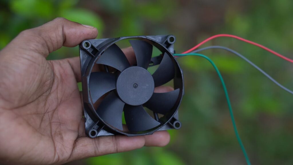
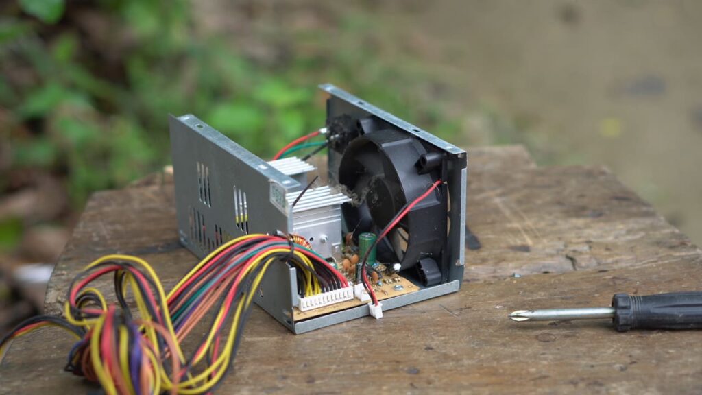
First, I’ll take a fan and take it all apart, and I’ll take out the film and the fan bushing that I need from it. I really need that.
Another thing you may know is that CPU fans usually have two-phase windings, so we will start with ESC, so for that, I need three-phase windings.
So I need three poles there, but you have four poles in the CPU fans. So, because of that, I can’t do three-phase windings; if there were six poles, I could have done waiting, so for that, I have to get one of my free poles.
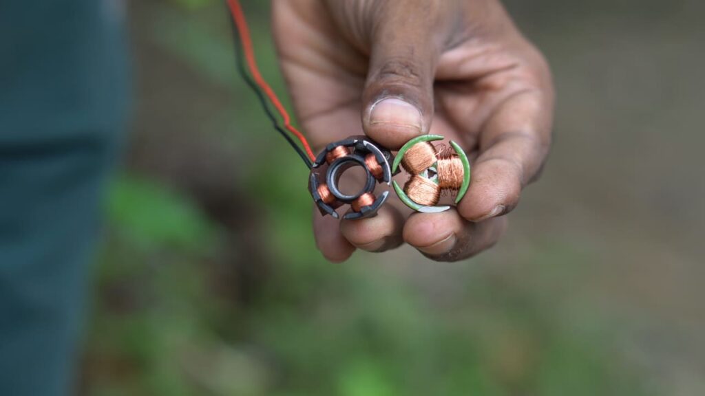
DC Motor Important
Now I will take a free pole DC motor. If I want to make 3 3-phase windings, I will need three full coils. So, for that, I am using a 12-volt DC motor. So I will disassemble it completely.
First, I will save the status flower with the Drill machine and attach the fan boost there and solder it.
Then I will strip off any old copper wire that may be left.
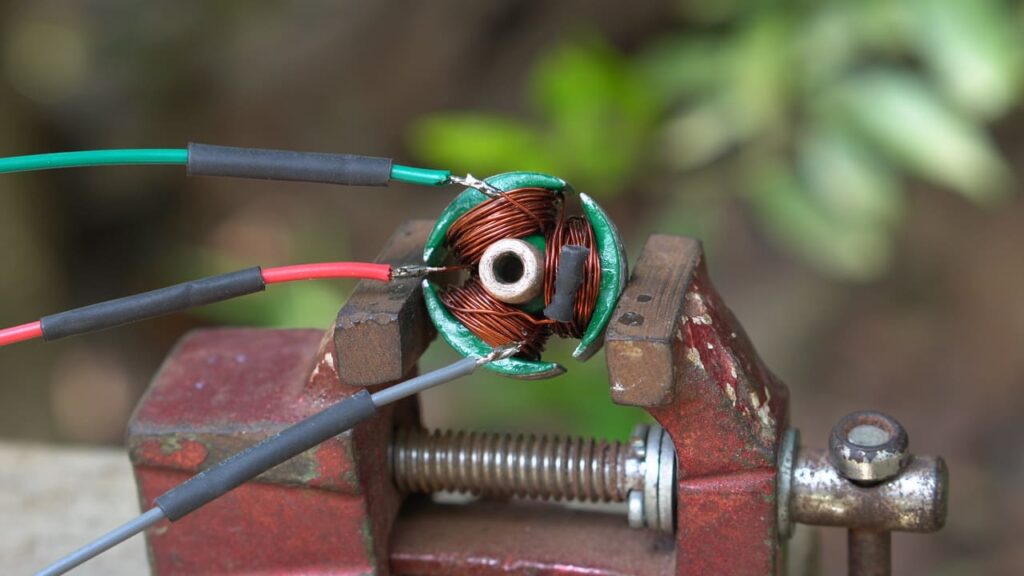
How to Make a 3-Phase Winding
I will use 0.4 mm copper wire for winding. I will complete the winding with fifty trains per pole. Now I will connect them all.
If you want, you can also do a delta connection, and you can do it with a Y connection, so here I am doing a Y connection. But it would be very good if you did a delta connection.
So this is how I made my BLDC motor, guys. You can see how I made a BLDC motor with a DC motor and a CPU fan, which will rotate at a very high speed, so let’s connect it now that we are here. So here I have used a phase and also used a 12-volt battery.
Register & Get $70 new user coupons at JLCMC
Industrial Automation and Manufacturing-Focused Online Supply Chain at JLCMC
#jlcmc #jlcmcmechanicalparts
5 Minute DC FAN UPGRADE to BLDC for MAX Performance Boost
While it’s a fascinating idea, directly converting a standard DC motor from a CPU fan into a 3-phase Brushless DC (BLDC) motor in full detail is generally not feasible for a few key reasons:
- Fundamental Differences:
- DC Motor: Uses brushes and a commutator to switch current to the windings, creating a magnetic field that interacts with permanent magnets on the rotor. The winding is typically on the rotor, and the magnets are on the stator.
- BLDC Motor: Eliminates brushes. The commutation is handled electronically by an external controller. The windings are typically on the stator, and permanent magnets are on the rotor.
- Physical Construction:
- Windings: A CPU fan DC motor usually has a simple winding configuration designed for DC operation. A 3-phase BLDC motor requires three distinct sets of windings, precisely wound and spaced around the stator.
- Magnets: A typical CPU fan motor might have an iron core rotor or a simple magnet structure. A BLDC motor needs specific permanent magnets (often neodymium) arranged in a particular pole configuration on the rotor.
- Sensors: BLDC motors often use Hall effect sensors (or sensorless control) to detect the rotor’s position, which is crucial for the electronic controller to know when to switch current to the correct windings. A standard DC motor lacks these.
- Electronic Control:
- A DC motor is controlled by varying the DC voltage.
- A BLDC motor requires a sophisticated Electronic Speed Controller (ESC) that takes DC power and converts it into precisely timed, commutated 3-phase AC-like waveforms to drive the motor windings based on rotor position.
What you can do, however, is understand the principles and potentially repurpose parts or build a very small custom BLDC motor from scratch.
Let’s break down the general process of making a 3-phase BLDC motor (not necessarily converting a DC CPU fan motor, but perhaps using its housing or shaft):
Components of a 3-Phase BLDC Motor:
- Stator: The stationary part. In a BLDC, this holds the windings.
- Rotor: The rotating part. In a BLDC, this holds the permanent magnets.
- Windings: Three sets of coils wound around the stator poles.
- Permanent Magnets: High-strength magnets on the rotor.
- Shaft and Bearings: For the rotor to spin smoothly.
- Electronic Speed Controller (ESC): The “brain” that drives the motor.
- Hall Effect Sensors (Optional but recommended for hobby builds): To detect rotor position for the ESC.
General Steps to Design and Build a Small BLDC Motor (Conceptual, not direct conversion):
Phase 1: Stator Construction
- Core Material: You’ll need a soft iron or silicon steel core for your stator. This could be salvaged from another small motor or even created by stacking thin laminations (like those found in transformers, though CPU fan motors don’t easily yield this). For a very tiny custom motor, you might even consider 3D printing a former and then inserting soft iron rods.
- Poles: The stator needs multiple “teeth” or poles where the coils will be wound. A common configuration is 9 or 12 stator poles for a 3-phase motor. For 9 poles, you’d have 3 poles per phase.
- Winding Calculation: This is critical and complex.
- Turns per Coil: Determines the motor’s Kv (RPM per Volt) and torque. More turns = lower Kv, higher torque.
- Wire Gauge: Determines current handling. Thicker wire = lower resistance, higher current.
- Winding Pattern: For 3-phase, you’ll need a specific pattern like ABCABCABC around the poles. Each “A” coil belongs to Phase A, “B” to Phase B, and “C” to Phase C. The coils for each phase are then connected in series or parallel to form the three main phase wires.
- Winding: Carefully wind insulated copper magnet wire around each pole. Ensure consistent tension and direction. For example, if you have 9 poles:
- Coil 1 (Phase A)
- Coil 2 (Phase C, reversed direction)
- Coil 3 (Phase B)
- Coil 4 (Phase A, reversed direction)
- …and so on.
- This is a simplified example; actual patterns like distributed winding or concentrated winding are used.
- Phase Connections: Connect the start and end of the coils for each phase. For example, connect all ‘A’ coils in series (or parallel) to form Phase A output. Do the same for B and C. This will give you three main wires (A, B, C) and a common neutral point if using a Wye (Star) connection, or just three wires if using Delta.
Phase 2: Rotor Construction
- Core Material: The rotor will typically be a non-magnetic material (like aluminum or plastic) to hold the magnets, attached to a central shaft.
- Permanent Magnets: This is crucial. You’ll need strong neodymium magnets. The number of magnets must be carefully chosen in relation to the number of stator poles. For a 9-pole stator, you might use 6 or 8 magnets (pairs of North/South poles).
- Magnet Placement: Securely attach the magnets to the rotor, alternating North and South poles. The air gap between the rotor magnets and the stator poles is critical for efficiency.
- Shaft & Bearings: Mount the rotor securely on a shaft, which will then be supported by bearings within the motor housing.
Phase 3: Sensor Integration (Optional, for sensored control)
- Hall Effect Sensors: If using sensored control, mount three Hall effect sensors around the stator, precisely spaced. They need to be positioned so that they trigger at specific points as the rotor magnets pass, indicating the rotor’s angular position.
- Magnet Placement: Ensure the rotor magnets pass over the Hall sensors at the correct times to provide accurate commutation signals.
Phase 4: Housing and Assembly
- Frame: You could try to use parts of the CPU fan housing as a frame, but it would likely require significant modification. A custom 3D printed housing is often used for small prototypes.
- Assembly: Assemble the stator, rotor, shaft, and bearings into the housing. Ensure the rotor spins freely without rubbing against the stator.
Phase 5: Electronic Speed Controller (ESC)
- Purchase an ESC: For a DIY BLDC motor, you will need to purchase an off-the-shelf 3-phase BLDC ESC. Designing and building an ESC from scratch is a highly complex electronics project involving microcontrollers, MOSFETs, and complex firmware for commutation, current control, and sometimes sensorless control algorithms.
- Connection: Connect the three motor phase wires (A, B, C) to the corresponding outputs on the ESC. Connect the Hall sensor wires (if used) to the ESC.
- Power: Provide DC power to the ESC.
- Control Input: The ESC will typically take a PWM (Pulse Width Modulation) signal from a microcontroller (like an Arduino) or an RC receiver to control the motor speed.
Why a CPU fan motor is difficult to convert directly:
- Stator Iron: The stator in a typical CPU fan is usually a simple stamped metal structure, often not designed for efficient magnetic flux path for multiple phases.
- Rotor Magnets: The rotor often has an integrated coil for DC operation or very weak/simple magnets. It’s not designed to house strong, precisely positioned permanent magnets.
- Space: The internal space is very limited, making it hard to wind three distinct phases or add Hall sensors.
What you could potentially salvage from a CPU fan:
- Bearings: Small bearings can be useful for custom projects.
- Shaft: The rotor shaft might be reusable for a very small custom BLDC motor.
- Outer Casing: Perhaps parts of the plastic housing could be adapted, but most internal components are specific to DC brush motor operation.
In conclusion, while the idea of converting a DC CPU fan motor is intriguing, the fundamental design differences make a direct conversion practically impossible without essentially building a new BLDC motor from scratch, albeit possibly reusing some structural elements like a shaft or bearings.
If you are interested in making a small BLDC motor, I would recommend looking into hobby projects that involve 3D printing custom stators and rotors and purchasing small neodymium magnets and an off-the-shelf ESC. This would be a more realistic and rewarding path than trying to dismantle and rewire a CPU fan’s DC motor into something it’s not designed to be.