I’ll demonstrate how to construct a straightforward yet potent audio amplifier using the TDA2003 integrated circuit (IC) in this blog post. Using an 18V DC supply voltage, the TDA2003 is a low-cost, high-performance amplifier that can send up to 10W of output power to a 4-ohm speaker. It can also be used in automobile audio applications with a 12V supply. The TDA 2003 includes a lot of features, including low harmonic and cross-over distortion as well as short-circuit and thermal overload safety.
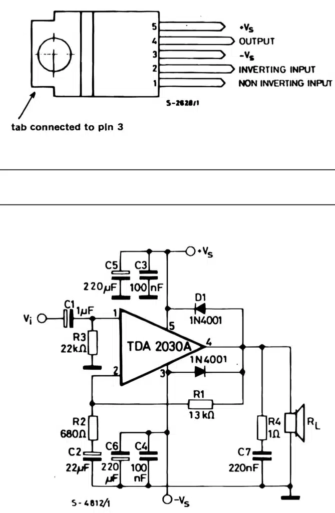
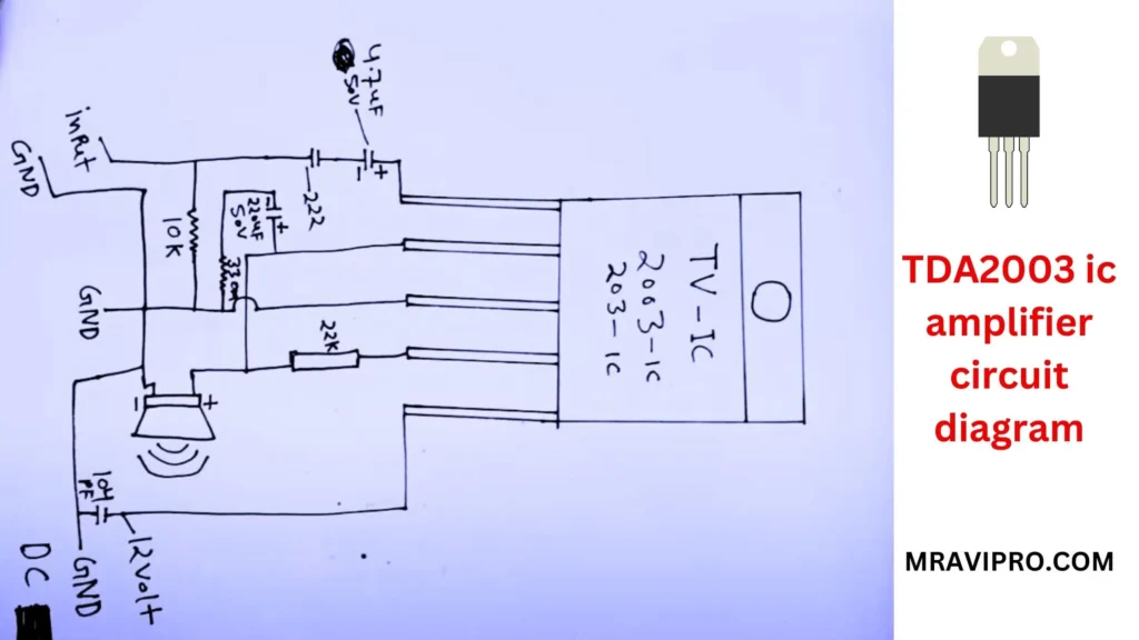
The amplifier’s circuit schematic is displayed below:
- 4.7UF capacitor
- 22.4UF capacitor
- 10K ohm resistor
- 104 UF ceramic capacitor
- 12V BETTREY
- TDA 2003
The circuit is based on the schematic provided in the TDA 2003 datasheet. By blocking any DC component, capacitor C7 couples the input signal to the IC’s non-inverting input. The voltage gain of the amplifier is controlled by resistors R2 and R3, according to the following formula:
Gain = 1 + (R3 / R2)
The gain for the values in the diagram is about 101. R2 and R3’s values control the gain, but to ensure equal gain on both channels, make sure they are low-tolerance metal film resistors. The lower cut-off frequency of the amplifier is determined by a high-pass filter made up of capacitor C3 and resistor R1, and it can be calculated using the following formula: TDA2003 ic Amplifier Circuit Diagram
F_L = 1 / (2 * pi * R1 * C3)
The lower cut-off frequency for the values in the diagram is roughly 16 Hz. By altering the values of R1 and C3, you can adjust this frequency, but you must make sure they stay within the datasheet’s advised range. The higher cut-off frequency of the amplifier is determined by a low-pass filter made up of capacitor C6 and resistor R4, which is specified by the formula:
F_H = 1 / (2 * pi * R4 * C6)
The upper cut-off frequency for the values in the diagram is roughly 20 kHz. By altering the values of R4 and C6, you can adjust this frequency, but you must make sure they stay within the datasheet’s advised range. Capacitor C5 connects the IC’s output to the speaker, which for best results has to be a 4-ohm, 10W speaker. Decoupling is provided by capacitors C1, C2, and C4 for the power supply, which for maximum output power needs to be a regulated 18V DC source. TDA2003 ic Amplifier Circuit Diagram
To build this amplifier, you will need the following components:
- TDA 2003 IC (1)
- 0.22-ohm resistor (2)
- 220-ohm resistor (1)
- 1-uF electrolytic capacitor (1)
- 100-uF electrolytic capacitor (3)
- 470-uF electrolytic capacitor (2)
- 100-nF ceramic capacitor (1)
- 4.7-nF ceramic capacitor (1)
- 4-ohm, 10W speaker (1)
- 18V DC power supply (1)
This circuit can also be assembled using a printed circuit board (PCB). On this page, you can find the PCB layout for this circuit. Ensure that the input ground and output ground are properly connected as per the diagram. To prevent overheating, be sure to attach a heat sink to the IC.
You may test this amplifier by plugging in an audio source, like an MP3 player or a smartphone, and adjusting the level with a potentiometer or variable resistor. The speaker should emit a loud and clear sound. Moreover, an oscilloscope and a multimeter can be used to measure the output power. The output power is calculated using the formula below:
- Also, Read This Article: 3.7Volt Li-ion Battery Charger Full Details & Solution.
- Also, Read This article: How to Make a BLDC Motor ESC Using MOSFET
- Also, Read This Article: 555 timer ic use throttle or accelerator sensor circuit diagram
- Also, Read This article: How to Make a BLDC Motor ESC Using MOSFET
- Also, Read This Article: 5V PWM Signal Booster Convert 12V PWM Signal Generator
- Also, Read This article: How to Make a BLDC Motor ESC Using MOSFET
- Also, Read This Article: RU6888r Mosfet Datasheet Full Details Download Free
P = V^2 / R
where R denotes the speaker’s resistance and V denotes the peak-to-peak voltage across it. For instance, the output power is as follows if you measure a peak-to-peak voltage of 12 volts across a 4-ohm speaker:
P = (12^2) / 4 = 36 / 4 = 9W
This is quite close to the 10 W maximum output power that an 18 V supply voltage is capable of producing.
I hope you had fun reading this article and learned how to construct a straightforward yet effective audio amplifier using the TDA2003 IC. Please use the space provided below to submit any queries or remarks. TDA2003 ic Amplifier Circuit Diagram
TDA2003 ic Amplifier Circuit Diagram Video:-
TDA2003 ic Amplifier Circuit Diagram