Hi, today I will show you how to make your DC motor into a BLDC motor and show you how to speed and boost it. Let’s get started. Earlier I have shown how to boost the speed of many bldc motors. If you want you can learn from my video or article later.
What Is Dc Motor and Its Working Principle?
An electrical device that transforms electrical energy from direct current into mechanical energy is called a DC motor. Its operation is predicated on the interaction of an electric current-carrying conductor with a magnetic field, which generates a mechanical force.
Inside the motor, a stationary magnetic field is created by permanent magnets or electromagnets (stator), and a current-carrying conductor (usually in the form of a coil wound around a rotor) is placed within this field.
When DC current flows through the conductor, it generates its own magnetic field.
The interaction between the stator’s magnetic field and the rotor’s magnetic field results in a force exerted on the conductor, as described by the Lorentz
force law: F=I( L× B), where B is the magnetic field, L is the conductor’s length vector, I is the current, and F is the force.
This force creates a torque that causes the rotor to rotate. Brushed DC motors employ a commutator and brushes to periodically reverse the direction of the current in the rotor, ensuring continuous rotation in a single direction.
windings as it rotates, thereby maintaining the torque in the same direction. 6 Brushless DC motors achieve this electronically.

What Is Bldc Motor and Its Working Principle
A Brushless DC (BLDC) motor is a type of synchronous electric motor powered by a DC voltage source, but unlike traditional brushed DC motors, it uses an electronic commutation system instead of mechanical brushes and a commutator.
The working principle of a BLDC motor also relies on the Lorentz force law, where a current-carrying conductor in a magnetic field experiences a force. In a BLDC motor, the permanent magnets are located on the rotor, and the stator contains the windings.
To create motion, the electronic controller energizes the stator windings in a specific sequence, producing a rotating magnetic field. This rotating magnetic field interacts with the magnetic field of the rotor’s permanent magnets, causing the rotor to rotate to align with the stator’s field.
The electronic controller precisely controls the timing and direction of the current flow to the stator windings based on the rotor’s position, which is typically sensed by Hall effect sensors or encoders.
By sequentially energizing the appropriate stator coils, the controller effectively “chases” the rotor’s magnetic field, resulting in continuous rotation with high efficiency and precise speed and torque control.
DC to BLDC Motor Make
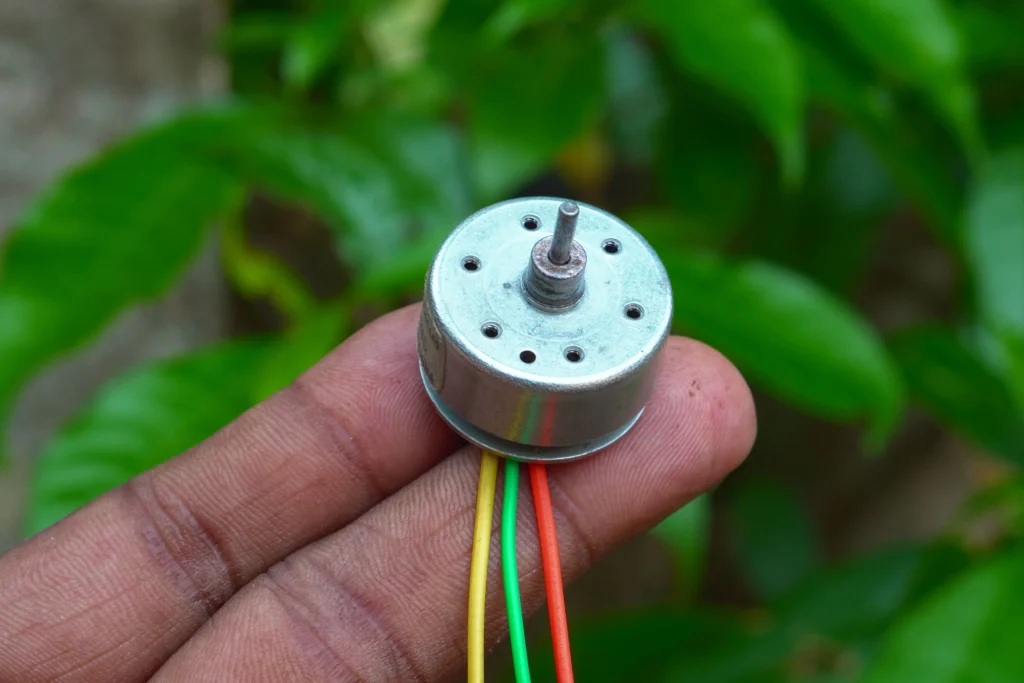
First I will take a 5 volt or 12 volt DC motor.
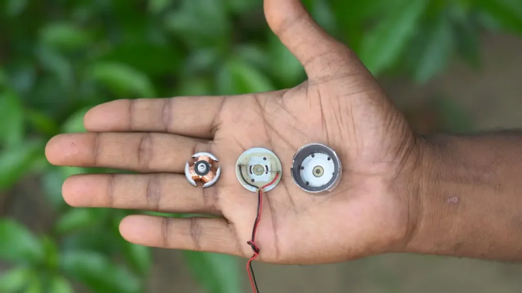
And I will disassemble the motor and remove its cover and turn it upside down and clean it and put a little bit of a bore so that it is easier for me to hold it.
And then I will remove the magnet from my router, rub the cover of the router a little, make it a little smaller, and then put the magnet back on it. This is how I will upgrade the DC to BLDC Motor. If you want, you can do it too.
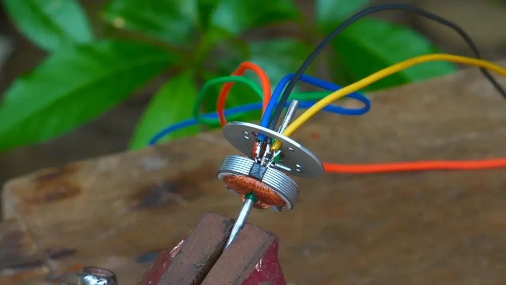
Dc to Bldc Motor Wire Jumper
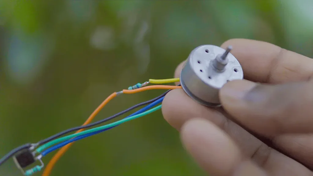
Now let’s solder the wires of the motor.
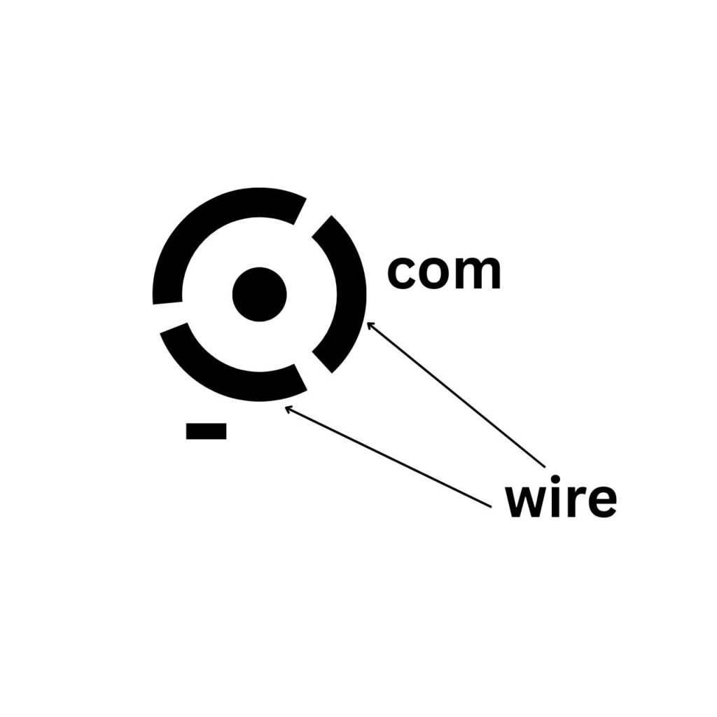
For that, we don’t know much about the motor, DC motor is made with 3 poles and its wires are also 3 wires, we will just solder the wires of 2 poles.
And I will make any one of those 2 wires + and I will make the rest of the wires -.
Let’s Make an ESC for DC to BLDC Motor
Friend, you will be surprised to know that I will make the ESC of this bldc motor a little differently, completely different.
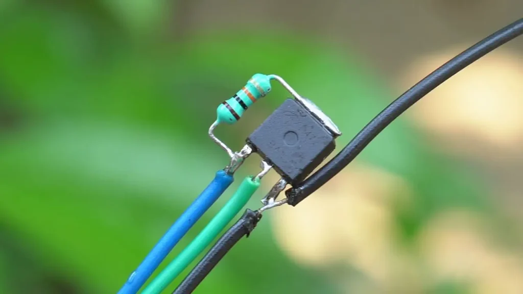
First I will take an
N – channel MOSFET.
And a 10k ohm resistor.
I will solder 10k ohm resistors to the gate pin and drain pin of the MOSFET. Our ESC made friends.
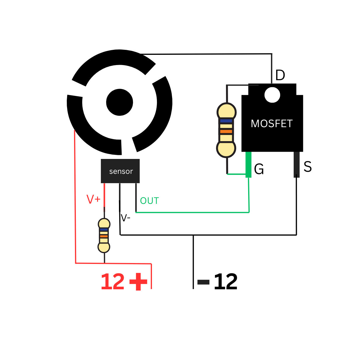
Hall Sensor in Bldc Motor and Schematic Diagram
EitherA 3-pin Hall sensor is a compact integrated circuit that detects the presence and strength of a magnetic field and typically has three terminals for power (VCC), ground (GND), and output.

Its operation is based on the “Hall effect” theory, which states that a voltage difference (Hall voltage) is created across a current-carrying conductor (inside the sensor) when it is put in a magnetic field perpendicular to the current. This voltage difference is perpendicular to both the current and the magnetic field.
The strength of the magnetic field directly correlates with the size of this Hall voltage.
In a 3-pin Hall sensor, the internal circuitry amplifies this small Hall voltage and provides a usable output signal.
This output can be either analog (a voltage proportional to the magnetic field strength) or digital (a switch that turns on or off when a certain magnetic field threshold is reached).
The specific function (analog or digital) depends on the internal design of the sensor. These sensors are widely used for non-contact sensing in various applications, including position sensing, speed detection, proximity sensing, and current sensing, due to their reliability, durability, and ability to operate in harsh environments.
- CPU FAN HIGH SPEED Bldc Motor Controller MAKE at HOME
- BLDC Cpu Fan Convert High Speed Bldc Motor With Controller Making || 5 Minute BLDC Upgrade for MAXIMUM Performance
- Upgrade Your Fan in 5 Minutes With This BLDC || How to Make Bldc Motor and Controller
- DC CDI Unit Wiring Diagram || Royal Enfield Bike Cdi Unit Wire Connection Diagram
- How to Make High Speed Bldc Turbo Jet Fan at Home