Stepper motors are an integral part of many hobbyist and engineering projects, known for their ability to rotate at precise angles and provide controlled movement. They are commonly utilised in 3D printers, CNC machines, and other automated equipment.
If you’re looking to maintain a stepper motor using an Arduino, the L293D motor driver is an excellent choice due to its ease of use and functionality.
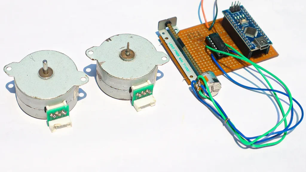
The L293D is a dual H-bridge motor driver integrated circuit (IC) that allows you to independently control the direction and speed of two DC motors.
It’s perfect for driving stepper motors as it can handle the current spikes that occur when the coils in the stepper motor are energized.
Here’s a step-by-step guide on how to control a stepper motor using the L293D driver and an Arduino:
Materials Needed:
- Arduino board (Uno, Mega, etc.)
- L293D motor driver IC
- Stepper motor (like the 28BYJ-48 or NEMA 17)
- External power supply (if required by the stepper motor)
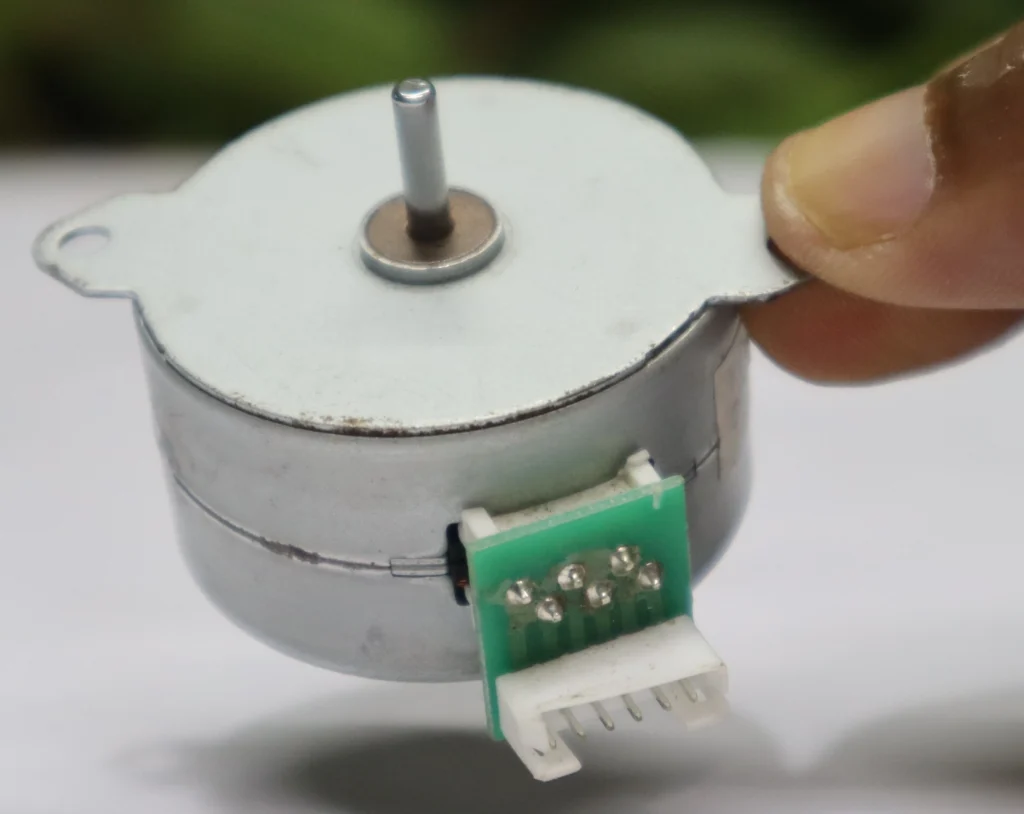
Understanding Your Stepper Motor
Before you begin, make sure you understand your stepper motor’s characteristics. Check the datasheet for the voltage and current requirements, the number of steps per revolution, and whether it’s a unipolar or bipolar motor.
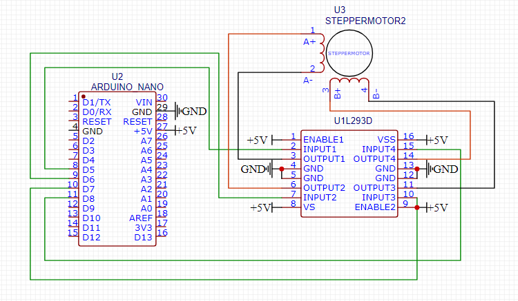
Wiring the Circuit
Connect the L293D to your Arduino and stepper motor. The L293D IC has 16 pins, with pins 1-8 on one side controlling one motor and pins 9-16 on the opposite side controlling another.
For a unipolar motor, you’ll connect four of the motor’s wires to the output pins on one side of the L293D. For a bipolar motor, you’ll use both sides of the L293D.
Powering the Driver
You may need an external power supply if your stepper motor requires more voltage or current than the Arduino can provide. Connect the external power to the L293D’s Vcc2 pin and the Arduino’s 5V output to the Vcc1 pin.
Programming the Arduino
Write a sketch to control the stepper motor. You’ll need to initialize four output pins to control the L293D’s input pins and create a function to sequence the activation of these pins. This sequence will make the motor revolve.
Testing Your Setup
Upload your code to the Arduino and test the stepper motor. Adjust the delay between steps to control the speed of the motor.
DVD Writer Stepper Motor Code.
#include <Stepper.h>

const int stepsPerRevolution = 2048;  // change this to fit the number of steps per revolution
// for your motor

// initialize the stepper library on pins 8 through 11:
Stepper myStepper(stepsPerRevolution, 5, 6, 7, 8);

void setup() {
  // set the speed at 60 rpm:
  myStepper.setSpeed(20);
  // initialize the serial port:
  Serial.begin(9600);
}

void loop() {
  // step one revolution  in one direction:
  Serial.println("clockwise");
  myStepper.step(stepsPerRevolution);
  delay(1000);

  // step one revolution in the other direction:
  Serial.println("counterclockwise");
  myStepper.step(-stepsPerRevolution);
  delay(1000);
}
NORMAL 5 VOLT SFR MOTOR CODE
#include <Stepper.h>

const int stepsPerRevolution = 200;  // change this to fit the number of steps per revolution
// for your motor

// initialize the stepper library on pins 8 through 11:
Stepper myStepper(stepsPerRevolution, 5, 6, 7, 8);

void setup() {
  // set the speed at 60 rpm:
  myStepper.setSpeed(5);
  // initialize the serial port:
  Serial.begin(9600);
}

void loop() {
  // step one revolution  in one direction:
  Serial.println("clockwise");
  myStepper.step(stepsPerRevolution);
  delay(1000);

  // step one revolution in the other direction:
  Serial.println("counterclockwise");
  myStepper.step(-stepsPerRevolution);
  delay(1000);
}
Fine-Tuning
Experiment with the code to achieve the desired motor speed and direction. You can also implement acceleration and deceleration for smoother movements.
For detailed tutorials and examples, you can refer to various online resources that provide in-depth explanations and code samples for controlling stepper motors with the L293D and Arduino.
By following these steps, you can successfully control a stepper motor for your project, creating precise and controlled movements. Whether you’re building a robot, a CNC machine, or any project requiring controlled motion, the combination of a stepper motor, L293D driver, and Arduino is a reliable and efficient solution.
- How To Make 3 Phase Bldc Motor Controller Using 555 Ic – With Back Emf
- I Made A Brushless Motor And Controller With Bike Dynamo
- BLDC Motor Controller (बीएलडीसी मोटर नियंत्रक) Circuit Download Free
- 12V-24V DC Motor Controller Using TL494 Circuit Diagram Download Free
How to control a stepper motor with L293D motor driver?
Controlling a stepper motor with an L293D motor driver involves connecting the motor to the driver and interfacing the driver with a microcontroller, such as an Arduino.
The L293D has two H-bridges, which are used to control the direction and speed of the motor by alternating the current flow through the motor’s coils.
For unipolar motors like the 28BYJ-48, you would connect the motor’s wires to the output pins of the L293D, and for bipolar motors like the NEMA 17, you would determine the wire connections based on the motor’s datasheet. The input pins of the L293D are then connected to the digital output pins of the Arduino, allowing for programmable control over the motor’s movements.
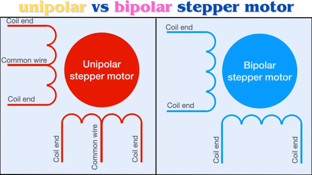
what is difference between unipolar and bipolar stepper motor
The primary difference between unipolar and bipolar stepper motors lies in their wiring and driving configurations. Unipolar motors have a single winding with a center tap per phase, allowing for simpler driving circuits since the current only needs to flow in one direction.
Bipolar motors, on the other hand, have no center tap and require current to flow in both directions, necessitating more complex driving circuits. This complexity allows bipolar motors to generate more torque and be more efficient, but at the cost of a more complicated control system.
What is a bipolar stepper motor?
A bipolar stepper motor is a type of electric motor that divides a full rotation into a number of equal steps.
The motor’s position can be commanded to move and hold at one of these steps without any feedback sensor, as the motor is precisely controlled by the current in the windings.
Bipolar motors have a single winding per phase, and the current in the winding needs to be reversed to change the motor’s direction, which requires a more complex driver circuit.
These motors are used in applications requiring precise control of motion, such as 3D printers, CNC machines, and robotics.
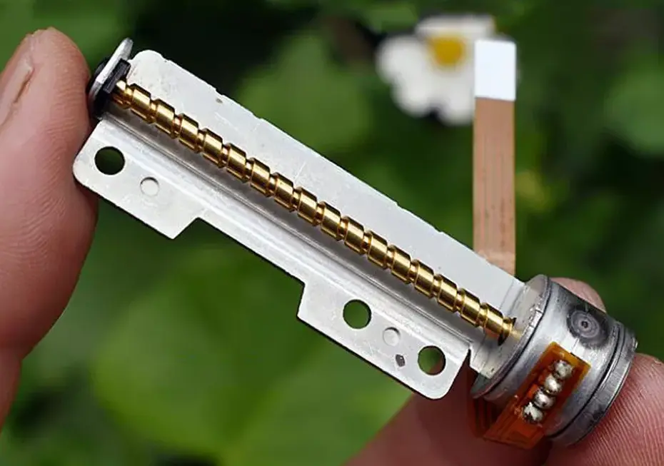
stepper motor working
A stepper motor is a type of electric motor that moves in discrete steps, allowing for precise control of the angular position. The core principle behind its operation is the use of electromagnets in the stator to create a magnetic field that causes the rotor to move to a specific position. By energizing the stator coils in a sequence, the motor’s rotor can be rotated in fixed increments, known as steps. This characteristic makes stepper motors ideal for applications where controlled movement is essential, such as in robotics, CNC machines, and 3D printers.