If you’re looking for 24V DC motor controller circuits of the highest caliber, we can provide you with a variety of circuits. But today I’ll demonstrate for you. For your selection, using TL494 and IRF1405 could be preferable.
Why it is unique. Consider a circuit that uses a low-voltage battery tester system, gentle starts, adjustable pulse frequencies, and currents up to 20A for 12V or 24V batteries.
And it is compact and uncomplicated. not having to write software (without a microcontroller). The major components are TL494, HEXFET, and LM2940.
TL494 IC 12V DC Motor Speed Control PWM Circuit Diagram
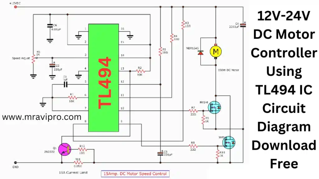
- For 12V, 150W, the maximum motor speed control is 15A.
- R6 speed-adjust motor
- Mosfet IRFZ48.x Driver Motor, 2 pieces
Control at 100 Hz (Hz) and change the PWM duty cycle from 0% to 100% - The rise and fall times are 10us.
- There is a 15A overload current or current limit, and R11 and Q1 are working to stop IC1
How to Control 24V DC Motor Speed
There are several methods to control the speed of a 24V DC motor, depending on your requirements and preferences. Here are a few of the most popular methods:
Using a generic analog DC motor speed controller: This is a simple and inexpensive way to control the speed of a motor by regulating the supply voltage with pulse width modulation (PWM).
You can use a potentiometer to manually adjust the speed of the motor in one direction. However, this method does not allow you to reverse the motor direction.
and it is not suitable for microcontroller control. You can find more details and a circuit diagram for this method in this tutorial.
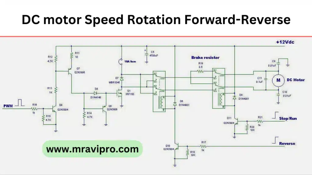
Using an H-bridge circuit: This is a more versatile way to control the speed and direction of a motor by switching the polarity of the supply voltage.
You can use four transistors or MOSFETs to form an H-bridge circuit and use PWM signals from a microcontroller to control the switching.
You can find more details and a circuit diagram for this method in this tutorial.
Using a motor driver: This is a convenient and reliable way to control the speed and direction of a motor by using a dedicated IC or module that integrates the H-bridge circuit and other features.
You can use a motor driver such as the L293D or L298N, which can handle up to 2A per channel, or a higher-current motor driver such as the BTS7960, which can handle up to 43A per channel.
You can connect the motor driver to a microcontroller and use PWM signals to control the speed and direction of the motor. You can find more details and examples of using different motor drivers in this tutorial.
12v–24v Dc Motor Using Tl494 and Irf1405 Circuit
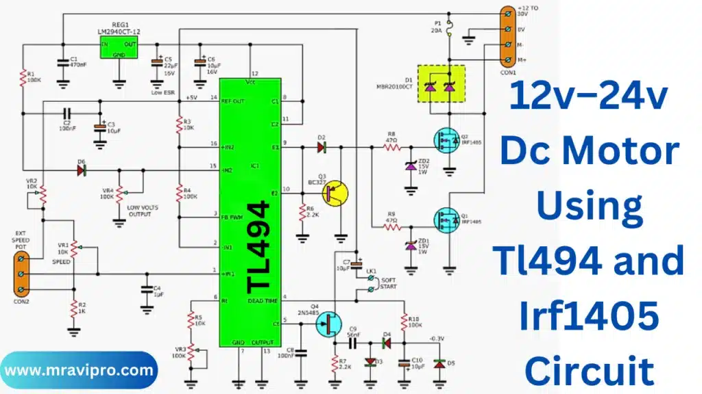
Schematic representation of the project. project attributes.
- 12V to 30V power supply range
- Maximum current usage: 20A
- Maximum current output: 20A
- 20mA for standby current
- Motor controller range: 0% to 100%
- Turn off the power when the battery voltage is lower. Set at 11.5V for 12V batteries and 23V for 24V batteries.
- Pulse frequency can be changed from roughly 100Hz to 1.1 kHz (129 Hz to 1.28 kHz in this project)
- Soft start: a range of 0 to 100% lasting less than one second MOSFET gate pulse rising-edge and falling-edge: 1.5 uS and 1.6 uS
- speed-controlled VR1
- speed-controlled VR1
- VR3: Adjust the output pulse frequency
- Speed controller for the VR2-sub
Note: I received this circuit from a buddy. It is a very effective high-current DC motor controller, he claimed. Yet it is an entire piece, not just a clear picture.
The Capacitors
- C1: 470nF, 63V, electric
- C2, C8: 100nF nF, 63 volts, electric
- C9: 56nF, 63V, electric
- C5: 22uF, 16 volts, Electrolytic
- C3,C6,C7,C10: 10uF uF, 16 volts, electrolytic
- C4: 1uF, 63V, Ceramic
Will you require parts?
- Pulse width modulation, IC1: TL494 (PWM)
- Regulator Q1, Q2: IRF1405, N-channel MOSFET, REG1: LM2940CT-12
- Q3: BC327, a 45 V, 800 m A PNP Transistor
- Q4: N-Channel FET, 2N5484
- D1: High-frequency Diode MBR20100CT
- 1N4148, 75V, 0.15A Diodes, D2-D6
- 1N4744, Zener Diode: ZD1, ZD2.
0.25W Resistor
- R1,R4,R10: 100K
- R3, R5, 10K, R6, and R7, 2.2K.
- R2: 1K
- 47 ohms for R8, R9
- 10K Trimpot VR1
- 10K Trimming Potentiometers for VR2
- 100K Trimmer Potentiometers for VR3, VR4,
- Potentiometer 10K
- the PCB, the heatsink, and additional components.
with a 20A short circuit protection 24V motor control
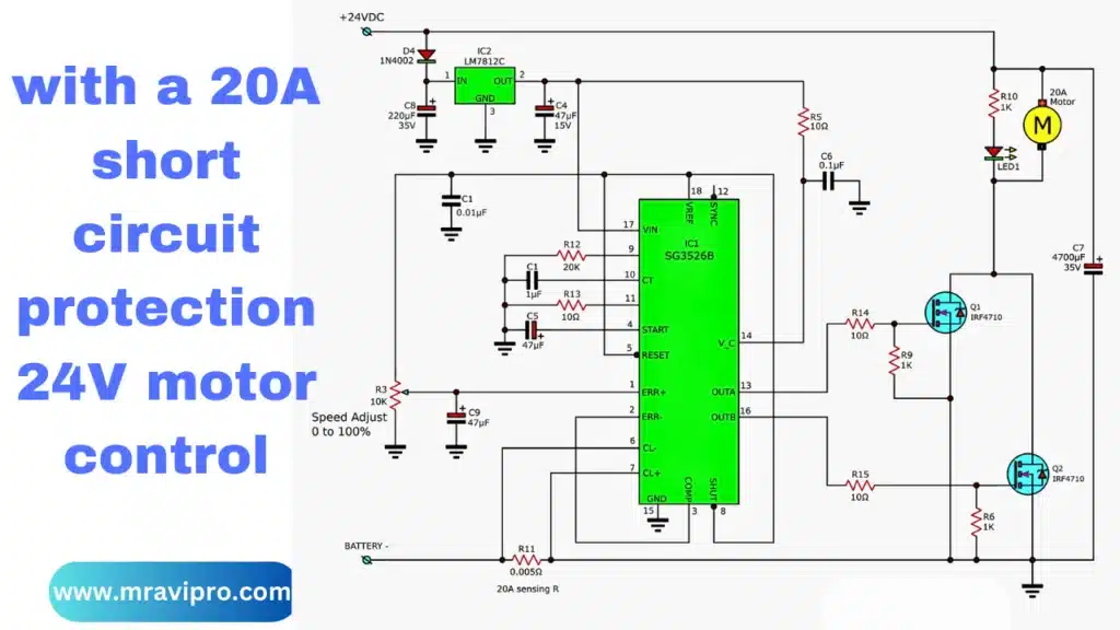
A 24V DC motor controller is being controlled by a 20Amp current. It does this by using the IC SG3526B to control the character PWM, which is very well received, and driving the motor with two IRFP7410 power Mosfets.
After you’re comfortable using a DC motor at 20 amps, you can use it while maintaining a short-circuit protection circuit. At the circuit, you can see the added detail.
12V-24V DC Motor Controller Diagram Download Free
If you are looking for a simple and effective way to control the speed of a DC motor using the PWM technique, then this article is for you. In this article, I will show you how to build a 12V–24V DC motor controller using the TL494 IC and a few other components. This circuit can handle up to 20A of current and can vary the speed of the motor from 0 to 100%. You can also adjust the frequency and the low-voltage protection of the circuit. The circuit diagram and the PCB layout are available for free download at the end of this article.
DC Motor Speed Control Using a Potentiometer
The basic principle of PWM (pulse width modulation) is to vary the duty cycle of a square wave signal that is applied to the motor.
By changing the ratio of the on and off times of the signal, we can control the average voltage and current that the motor receives. This then has an impact on the motor’s speed and torque.
The TL494 IC is a versatile PWM controller that can generate two complementary or single-ended output signals with variable duty cycle and frequency.
It also has two error amplifiers, an internal 5V reference, a dead time control, and an output control circuit.
The TL494 IC can be easily configured to control a DC motor using a potentiometer.
The circuit diagram of the 12V–24V DC motor controller using the TL494 IC is shown below:
- The input voltage can be either 12V or 24V DC. The LM2940CT-12 regulator provides a stable 12V supply for the TL494 IC and the error amplifiers.
- The error amplifiers compare the feedback voltage from the motor with the reference voltage from the internal regulator. The feedback voltage is proportional to the speed of the motor and is obtained by dividing the output voltage with R9 and R10. The reference voltage is set by VR1 and VR2. The difference between these two voltages determines the duty cycle of the output signals from the TL494 IC.
- The output signals from the TL494 IC are fed to the gates of Q1 and Q2 through R11 and R12. These MOSFETs act as switches that connect and disconnect the motor from the supply voltage. The diode D1 prevents the reverse current from flowing back to the supply when the MOSFETs are off.
- The frequency of the output signals from the TL494 IC is set by RT and CT. VR3 can be used to adjust the frequency from about 100 Hz to 1.1 kHz.
- The dead-time control (DTC) comparator ensures that there is a small delay between turning off one MOSFET and turning on another. This prevents short circuits and improves efficiency. The dead time is fixed at about 5% by R13 and C9.
- The output control circuit selects either single-ended or push-pull operation for the output signals. In single-ended mode, only one MOSFET is switched on at a time, while in push-pull mode, both MOSFETs are switched on alternately. The output control pin is connected to the ground through R14 for single-ended mode. For push-pull mode, R14 can be removed or replaced with a jumper wire.
- The low-voltage protection circuit monitors the input voltage and shuts off the output signals when it falls below a certain level. This prevents damage to the battery and the motor due to over-discharge. The low-voltage threshold is set by VR4 and ZD1. For a 12V battery, the threshold is about 11.5V, and for a 24V battery, it is about 23V. Q3 and Q4 form a switch that turns off the error amplifiers when the input voltage is too low.
- The motor is connected to the output terminals of the circuit. The speed of the motor can be controlled by VR1 and VR2. VR1 sets the maximum speed, while VR2 sets the minimum speed. The motor can be stopped by turning VR2 fully clockwise.
The PCB layout of the 12V-24V DC motor controller using the TL494 IC is shown below:
The PCB layout is designed for a single-sided board. The components are placed on the top side, while the traces are on the bottom side. The board size is about 10cm by 6cm.
You can download the circuit diagram and the PCB layout files from the following link:
12V-24V DC Motor controller using TL494 IC circuit diagram Download Free
I sincerely hope you find this essay interesting and helpful. Please don’t hesitate to leave a comment below if you have any questions or recommendations. Happy construction!