Original ESC Make Guide
A 40A sensorless BLDC motor speed controller can be built using a microcontroller (like an Arduino), MOSFETs for switching, and a gate driver IC for efficient switching. The controller uses back EMF (BEMF) sensing to determine rotor position and commutate the motor phases. A PWM signal from the microcontroller controls the speed by varying the duty cycle.
- How to Make High Speed Bldc Turbo Jet Fan at Home
- 5 Minute DC to BLDC Motor Upgrade for MAXIMUM Best Performance
- CPU FAN HIGH SPEED Bldc Motor Controller MAKE at HOME
- BLDC Cpu Fan Convert High Speed Bldc Motor With Controller Making || 5 Minute BLDC Upgrade for MAXIMUM Performance
Microcontroller:
An Arduino 328p or similar microcontroller handles the control logic, receiving user input (e.g., speed setting) and generating PWM signals for the MOSFETs.
Gate Driver IC:
These ICs (e.g., IR2104S) amplify the microcontroller’s signals to efficiently switch the high-current MOSFETs.
MOSFETs:
These act as electronic switches to control the current flow to the motor windings. High-side and low-side MOSFETs are used for each phase.
Back EMF Sensing Circuit:
The back EMF produced by the motor windings is detected using a voltage divider and comparator (such as the analog comparator on the Arduino). In a sensorless system, this is essential for figuring out the rotor position.
PWM Generation:
The microcontroller generates PWM signals, typically with a frequency range of 10-36 kHz, to control the speed of the motor by varying the duty cycle.
Power Supply:
A suitable DC power supply (e.g., 12V, 24V, or higher) is needed to power the motor and the controller circuitry.
Protection Circuitry:
Consider adding flyback diodes and current-limiting resistors to protect the MOSFETs and other components from voltage spikes and overcurrent conditions.
Sensorless Control Algorithm:
Initial Commutation:
At startup, a predefined sequence of switching is used to get the motor rotating. This sequence is based on assumptions about the rotor position.
Back EMF Detection:
As the motor spins, the back EMF generated in the windings is sensed by the comparator circuit. The rotor’s position in relation to the stator windings is indicated by this signal.
Rotor Position Estimation:
By analysing the timing and amplitude of the back EMF signals, the microcontroller can estimate the rotor position. This allows for accurate commutation of the motor phases.
PWM Control:
The PWM signal is then adjusted based on the estimated rotor position to maintain smooth and efficient motor operation.
Important Considerations:
Motor Parameters:
The controller’s design (e.g., MOSFET selection, gate driver voltage) needs to be adapted to the specific motor being used, taking into account its voltage, current, and speed specifications.
Noise and EMI:
Sensorless control can be sensitive to noise and electromagnetic interference (EMI). Proper shielding and filtering techniques may be necessary.
Tuning:
The performance of a sensorless controller often requires fine-tuning of parameters like PWM frequency, back EMF detection thresholds, and commutation timing.
Current Limiting:
For a 40A controller, robust current limiting and protection mechanisms are essential to prevent damage to the motor and controller in case of overloads or short circuits.
Closed-Loop Control:
While this describes a sensorless open-loop system, closed-loop control using a PID controller can be implemented for more precise speed and position control.
Components List:
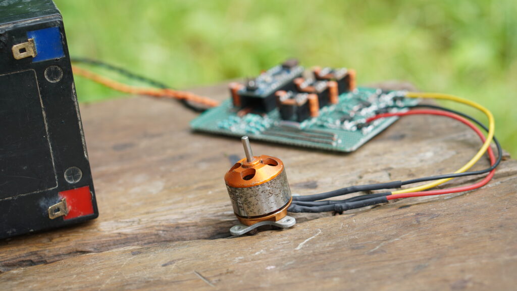
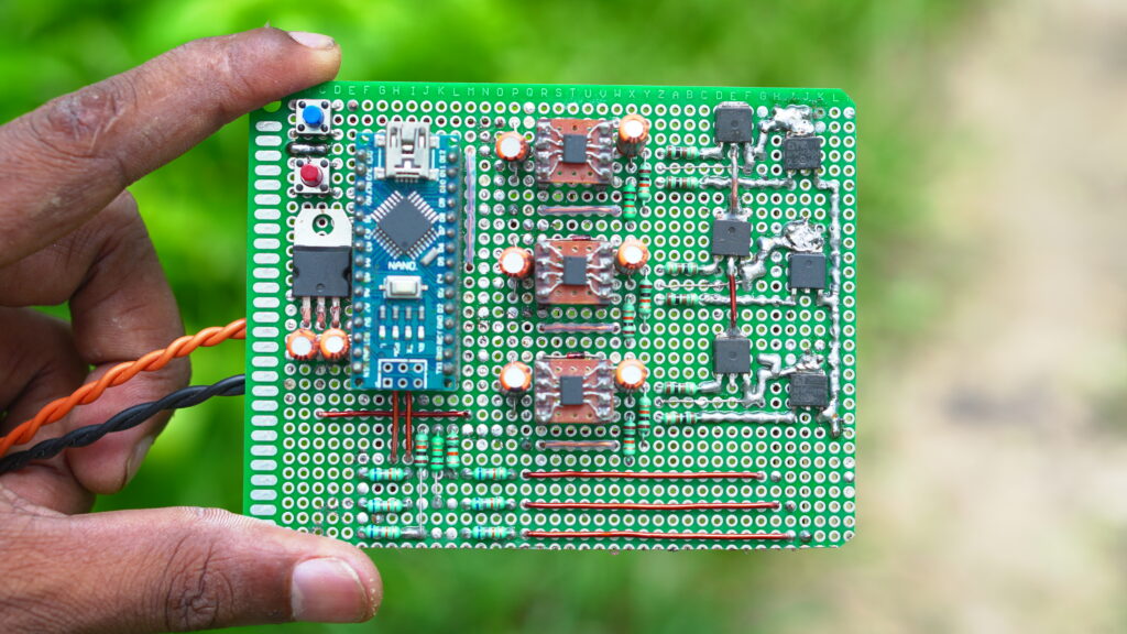
- Arduino Nano ATmega328P
- Brushless DC (BLDC) motor
- 6 x Irfz44n N-type mosfet
- 3 x IR2104S (IR2104s) gate driver IC #(ONLY SMD USE)
- 6 x 68k ohm resistor
- 3 x 10k ohm resistor
- 6 x 100-ohm resistor
- 3 x IN4148 diode
- 3 x 10uF capacitor
- 3 x 2.2 uF capacitor
- 2 x pushbutton
- 12V source
- PCB board
High-Speed 40a Bldc Motor Speed Controller Circuit Diagram
The circuit diagram of this project is given below:
Now let’s describe it and see what components were used to make this circuit.
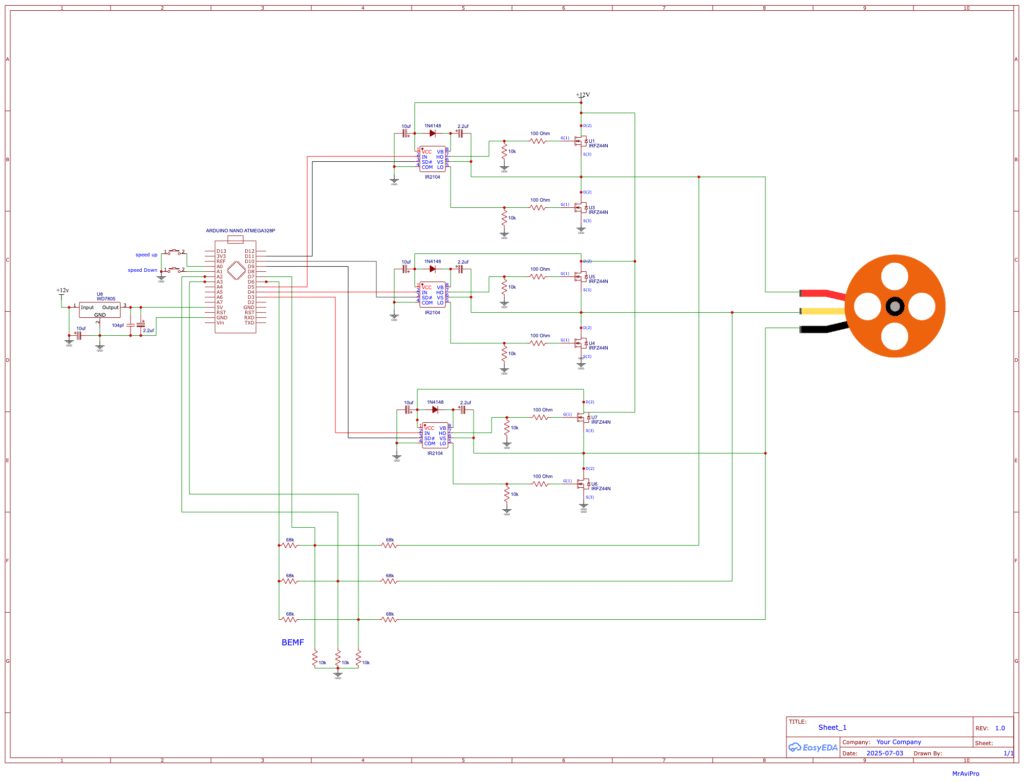
First of all, let me say that I connected all the ground connections together.
In this circuit I have used two push buttons, one for increasing the speed and the other for decreasing the speed. You can control the speed of the BLDC motor using these push buttons if you want.
Let’s say the first three 68k resistors (which will be connected to the motor phase) and the three 10k resistors are used as voltage dividers, because we can’t let the microcontroller supply 12V; the other three 68k resistors will create a virtual neutral point. We will connect the virtual neutral point to Arduino pin 6.
The ATmega328P microprocessor is the foundation of the Arduino Nano.
There is an analog comparator. 1 pin (6) (AIN0) on the Arduino Nano serves as the comparator’s positive input, while pins (7) (AIN1), A0 (ADC0), A1 (ADC1), A2 (ADC2), A3 (ADC3), A4 (ADC4), or A5 (ADC5) can serve as its negative input.
I will also link the 2 virtual neutral points to the positive pin (pin 6) of the analog comparator, in addition to attaching phase A BEMF to pin 7 (AIN1), phase B BEMF to pin A2, & phase C BEMF to pin A3.
The comparator uses software to compare the virtual point with the BEMF of a single phase each time. This makes the circuit simpler and requires less hardware.
The Friend IR2104S IC is used to activate and deactivate the high-side and low-side MOSFET of each phase. The switching between the high side and the low side follows the control lines IN-HIGH and SD-LOW.
Look at the High and Low Side Signal Diagram:
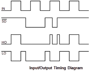
As you know, the IR2104S IC is used to drive a MOSFET.
Connect the SD lines of the IR2104S to the ADR NANO PIN (11, 10, 9).
Connect the IN lines of the IR2104S to the ADR NANO PIN (5, 4, 3).
BLDC Motor Controller Arduino Code:
/* How to Make a High-Speed 40a BLDC Motor Speed Controller Without Sensor*/

#define SPEED_UP          A0
#define SPEED_DOWN        A1
#define PWM_MAX_DUTY      255
#define PWM_MIN_DUTY      50
#define PWM_START_DUTY    100

byte bldc_step = 0, motor_speed;
unsigned int i;
void setup() {
  DDRD  |= 0x38;           // Configure pins 3, 4 and 5 as outputs
  PORTD  = 0x00;
  DDRB  |= 0x0E;           // Configure pins 9, 10 and 11 as outputs
  PORTB  = 0x31;
  // Timer1 module setting: set clock source to clkI/O / 1 (no prescaling)
  TCCR1A = 0;
  TCCR1B = 0x01;
  // Timer2 module setting: set clock source to clkI/O / 1 (no prescaling)
  TCCR2A = 0;
  TCCR2B = 0x01;
  // Analog comparator setting
  ACSR   = 0x10;           // Disable and clear (flag bit) analog comparator interrupt
  pinMode(SPEED_UP,   INPUT_PULLUP);
  pinMode(SPEED_DOWN, INPUT_PULLUP);
}
// Analog comparator ISR
ISR (ANALOG_COMP_vect) {
  // BEMF debounce
  for(i = 0; i < 10; i++) {
    if(bldc_step & 1){
      if(!(ACSR & 0x20)) i -= 1;
    }
    else {
      if((ACSR & 0x20))  i -= 1;
    }
  }
  bldc_move();
  bldc_step++;
  bldc_step %= 6;
}
void bldc_move(){        // BLDC motor commutation function
  switch(bldc_step){
    case 0:
      AH_BL();
      BEMF_C_RISING();
      break;
    case 1:
      AH_CL();
      BEMF_B_FALLING();
      break;
    case 2:
      BH_CL();
      BEMF_A_RISING();
      break;
    case 3:
      BH_AL();
      BEMF_C_FALLING();
      break;
    case 4:
      CH_AL();
      BEMF_B_RISING();
      break;
    case 5:
      CH_BL();
      BEMF_A_FALLING();
      break;
  }
}

 void bldc_move_reverse(){        // BLDC motor commutation function
  switch(bldc_step){
    case 5:
      AH_BL();
      BEMF_C_RISING();
      break;
    case 4:
      AH_CL();
      BEMF_B_FALLING();
      break;
    case 3:
      BH_CL();
      BEMF_A_RISING();
      break;
    case 2:
      BH_AL();
      BEMF_C_FALLING();
      break;
    case 1:
      CH_AL();
      BEMF_B_RISING();
      break;
    case 0:
      CH_BL();
      BEMF_A_FALLING();
      break;
  }
}
void loop() {
  SET_PWM_DUTY(PWM_START_DUTY);    // Setup starting PWM with duty cycle = PWM_START_DUTY
  i = 5000;
  // Motor start
  while(i > 100) {
    delayMicroseconds(i);
    bldc_move();
    bldc_step++;
    bldc_step %= 6;
    i = i - 20;
  }
  motor_speed = PWM_START_DUTY;
  ACSR |= 0x08;                    // Enable analog comparator interrupt
  while(1) {
    while(!(digitalRead(SPEED_UP)) && motor_speed < PWM_MAX_DUTY){
      motor_speed++;
      SET_PWM_DUTY(motor_speed);
      delay(100);
    }
    while(!(digitalRead(SPEED_DOWN)) && motor_speed > PWM_MIN_DUTY){
      motor_speed--;
      SET_PWM_DUTY(motor_speed);
      delay(100);
    }
  }
}

void BEMF_A_RISING(){
  ADCSRB = (0 << ACME);    // Select AIN1 as comparator negative input
  ACSR |= 0x03;            // Set interrupt on rising edge
}
void BEMF_A_FALLING(){
  ADCSRB = (0 << ACME);    // Select AIN1 as comparator negative input
  ACSR &= ~0x01;           // Set interrupt on falling edge
}
void BEMF_B_RISING(){
  ADCSRA = (0 << ADEN);   // Disable the ADC module
  ADCSRB = (1 << ACME);
  ADMUX = 2;              // Select analog channel 2 as comparator negative input
  ACSR |= 0x03;
}
void BEMF_B_FALLING(){
  ADCSRA = (0 << ADEN);   // Disable the ADC module
  ADCSRB = (1 << ACME);
  ADMUX = 2;              // Select analog channel 2 as comparator negative input
  ACSR &= ~0x01;
}
void BEMF_C_RISING(){
  ADCSRA = (0 << ADEN);   // Disable the ADC module
  ADCSRB = (1 << ACME);
  ADMUX = 3;              // Select analog channel 3 as comparator negative input
  ACSR |= 0x03;
}
void BEMF_C_FALLING(){
  ADCSRA = (0 << ADEN);   // Disable the ADC module
  ADCSRB = (1 << ACME);
  ADMUX = 3;              // Select analog channel 3 as comparator negative input
  ACSR &= ~0x01;
}

void AH_BL(){
  PORTB  =  0x04;
  PORTD &= ~0x18;
  PORTD |=  0x20;
  TCCR1A =  0;            // Turn pin 11 (OC2A) PWM ON (pin 9 & pin 10 OFF)
  TCCR2A =  0x81;         //
}
void AH_CL(){
  PORTB  =  0x02;
  PORTD &= ~0x18;
  PORTD |=  0x20;
  TCCR1A =  0;            // Turn pin 11 (OC2A) PWM ON (pin 9 & pin 10 OFF)
  TCCR2A =  0x81;         //
}
void BH_CL(){
  PORTB  =  0x02;
  PORTD &= ~0x28;
  PORTD |=  0x10;
  TCCR2A =  0;            // Turn pin 10 (OC1B) PWM ON (pin 9 & pin 11 OFF)
  TCCR1A =  0x21;         //
}
void BH_AL(){
  PORTB  =  0x08;
  PORTD &= ~0x28;
  PORTD |=  0x10;
  TCCR2A =  0;            // Turn pin 10 (OC1B) PWM ON (pin 9 & pin 11 OFF)
  TCCR1A =  0x21;         //
}
void CH_AL(){
  PORTB  =  0x08;
  PORTD &= ~0x30;
  PORTD |=  0x08;
  TCCR2A =  0;            // Turn pin 9 (OC1A) PWM ON (pin 10 & pin 11 OFF)
  TCCR1A =  0x81;         //
}
void CH_BL(){
  PORTB  =  0x04;
  PORTD &= ~0x30;
  PORTD |=  0x08;
  TCCR2A =  0;            // Turn pin 9 (OC1A) PWM ON (pin 10 & pin 11 OFF)
  TCCR1A =  0x81;         //
}

void SET_PWM_DUTY(byte duty){
  if(duty < PWM_MIN_DUTY)
    duty  = PWM_MIN_DUTY;
  if(duty > PWM_MAX_DUTY)
    duty  = PWM_MAX_DUTY;
  OCR1A  = duty;                   // Set pin 9  PWM duty cycle
  OCR1B  = duty;                   // Set pin 10 PWM duty cycle
  OCR2A  = duty;                   // Set pin 11 PWM duty cycle
}
How to Make a High-Speed 40a BLDC Motor Speed Controller Without Sensor Free