Hello friends, how are you all? Today, I’m going to show you how to convert a standard ceiling fan into a BLDC ceiling fan—right at home using DIY methods. So, let’s get started on transforming a regular ceiling fan into a BLDC one, using only materials available at home.
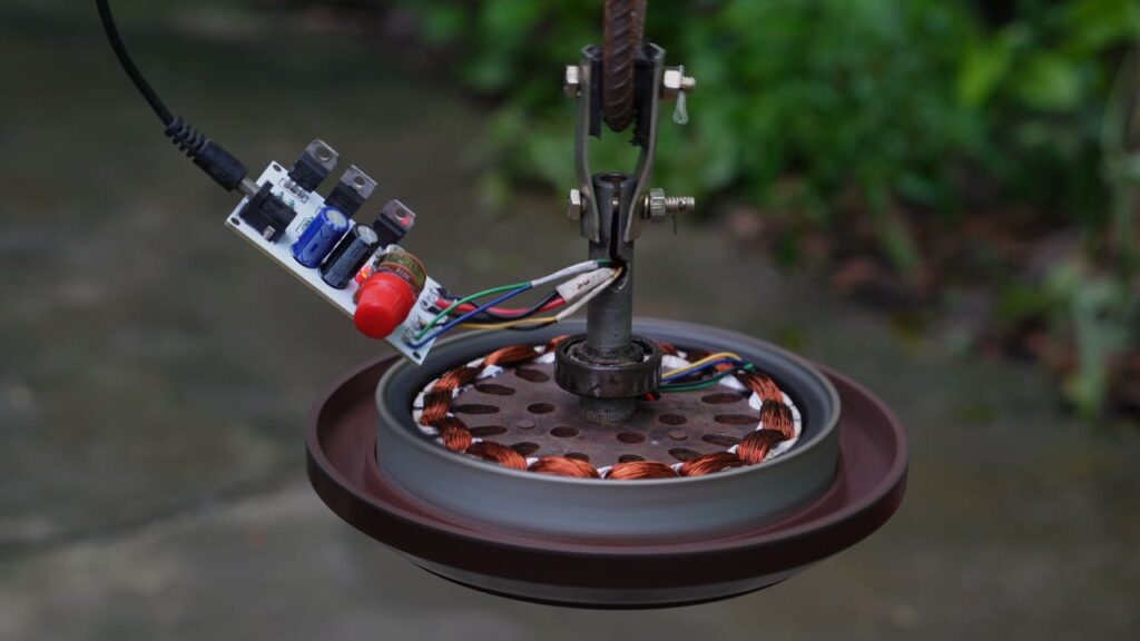
Which ceiling fans can be converted into BLDC ceiling fans?
As you can see, I am using a standard ceiling fan here; this is a 14-pole model, but you can use a 12-pole, 14-pole, or 18-pole fan if you wish.
I will cut off the old wires from this stator and clean it thoroughly.
Then, as you can see, I will apply PVC paper where the coil is to be wound, so that the iron core does not cut the wire. Here, you can see that I am using a 14-pole ceiling fan.
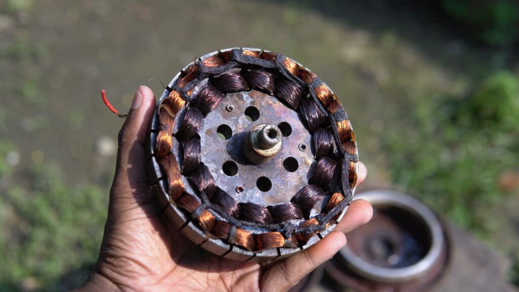
We will now learn about the wire used for winding and the winding process itself.
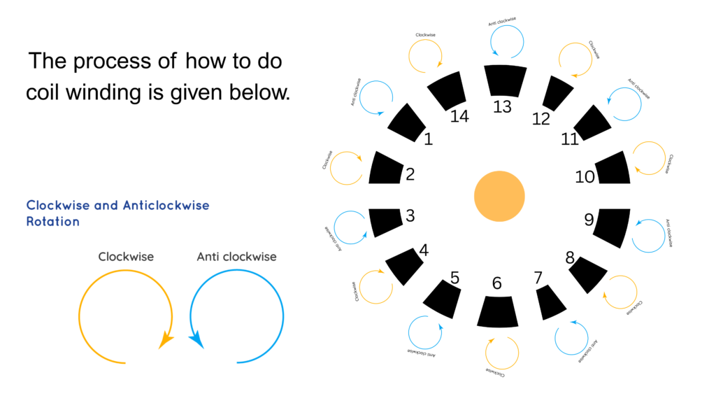
First, I will take 27-gauge copper wire and wrap it around each coil, alternating the direction—clockwise and counter-clockwise—as I proceed.
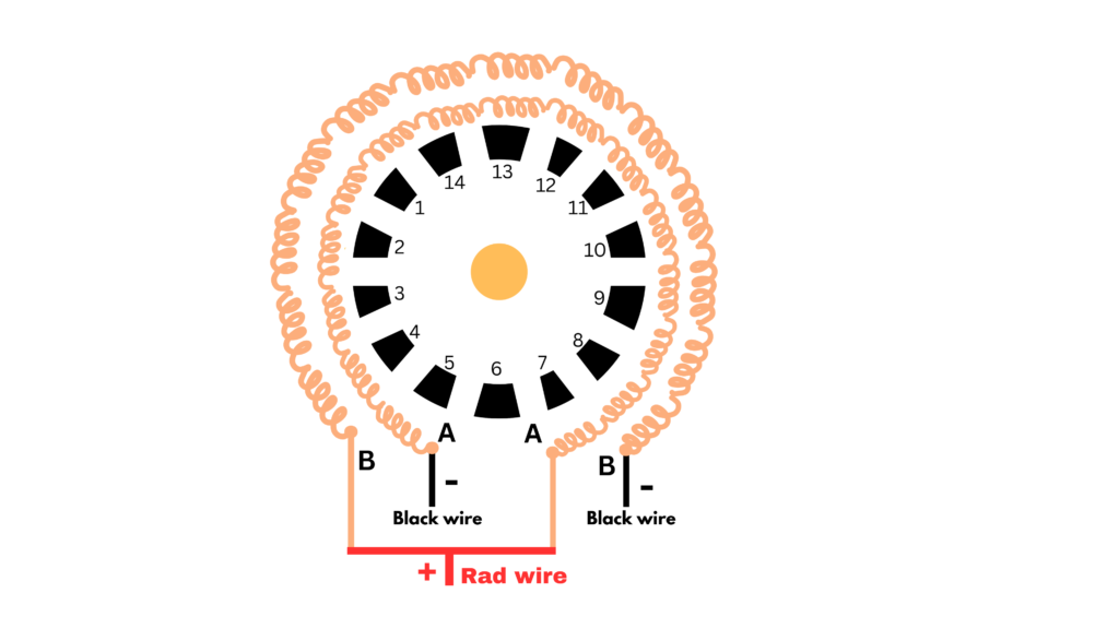
I will complete the entire winding process in this manner and then demonstrate how to make the connections; please refer to the provided image to understand how the wires have been connected.
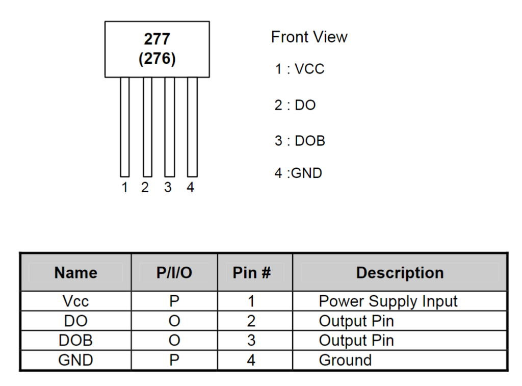
Now, we will learn about Hall sensors—specifically, four-pin Hall sensors.
You may be aware that a CPU fan contains a Hall sensor; here, I am using a four-pin Hall sensor, but the motor is a two-phase type.
For a two-phase motor, a sensor is required that can provide two signals from a single unit.
You can supply 5V, 9V, or 12V to the Hall sensor unit shown here; however, applying a higher voltage will damage the component. Therefore, to avoid any risk of damage, I recommend supplying 5V or 9V to its VCC pin.
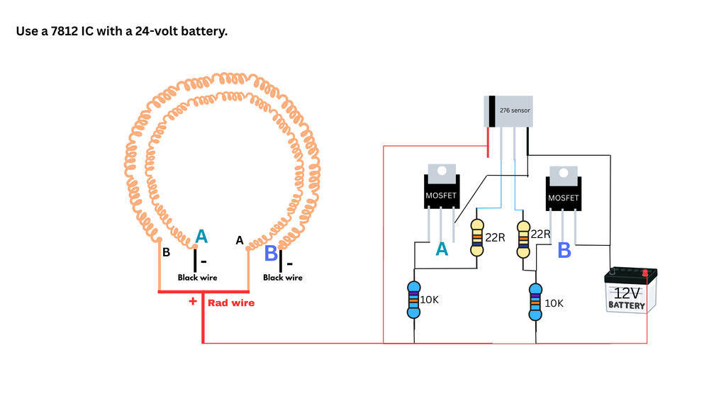
Now we will learn how a circuit diagram works.
The list of components is provided below, so I will not discuss them in further detail; however, I will explain the basic operating principle of the motor.
As I mentioned earlier, I am using a 14-pole stator coil setup with 14 standard magnets. Since my motor is a two-phase type, I need a sensor that is capable of producing two separate signals.
A CPU fan has a sensor that produces two separate signals at different times. I am explaining how my motor works using this setup.
When a magnet approaches the Hall sensor, one of the sensor’s pins is activated; the resulting voltage pulse triggers the gate of the MOSFET, which turns on the connection between the drain and source.
This sends a voltage signal to the motor, causing the motor to rotate once. When the next magnet approaches the sensor, the previously activated pin is turned off and a new pin is activated, sending another trigger pulse.
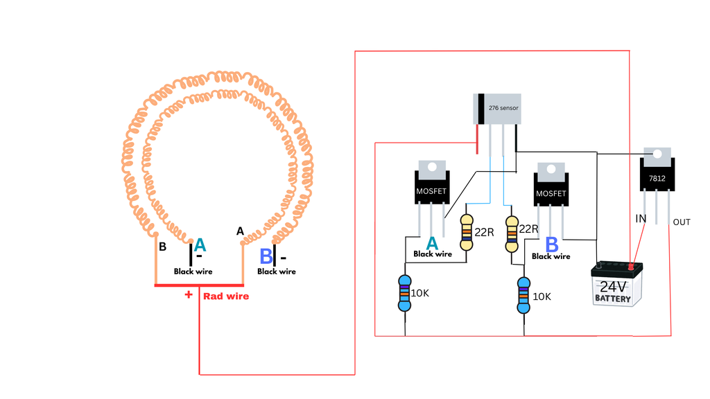
Through this repetitive switching process, the motor continues to rotate. Here is the circuit diagram of this two-phase motor; now that you understand how the motor works, you can build it yourself.
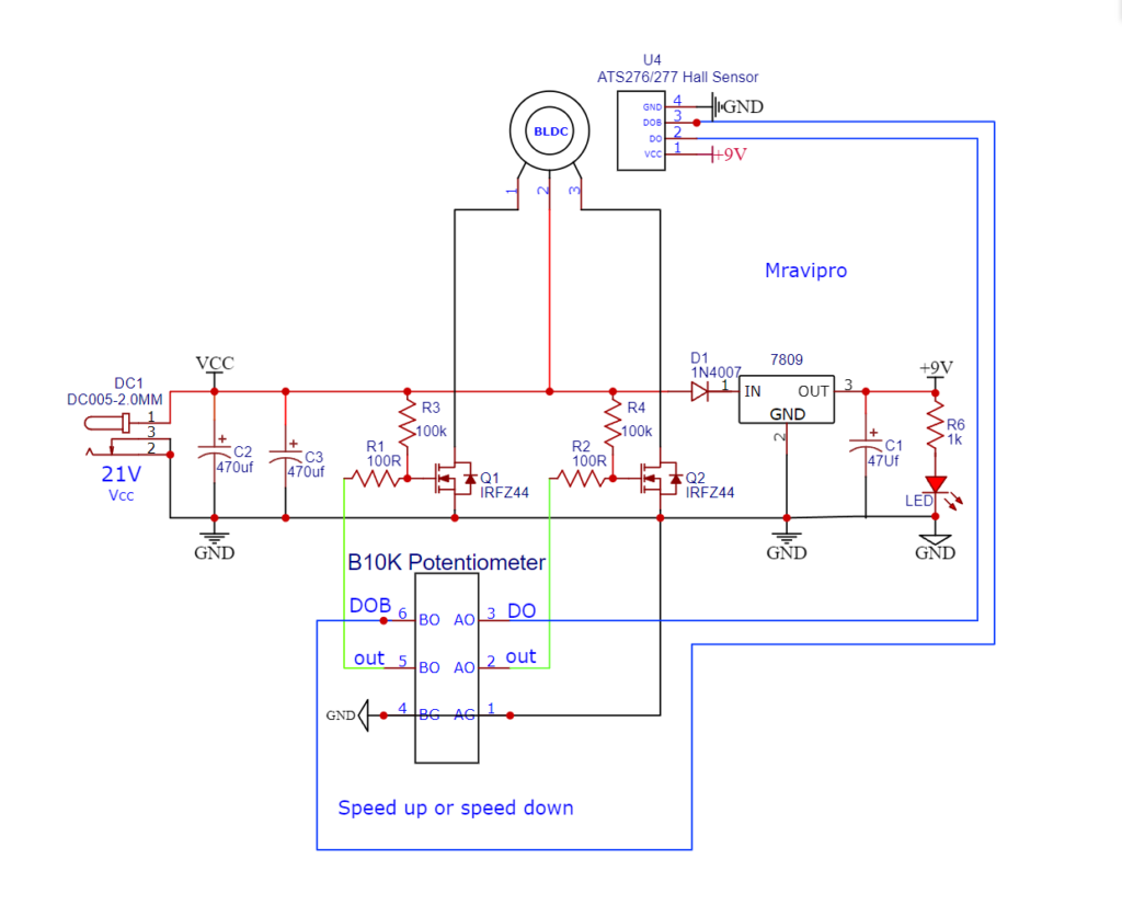
The circuit diagram shown above operates within the 21V to 35V range. If you wish to run it at 35V, you must replace the current 7805 regulator with another one—such as the 7824—and then convert the output to 5V; this is how you can operate it.
If you do not make this change, the motor will not run even if everything else is correct, because the MOSFET’s gate pin will not be triggered. Therefore, regardless of whether you are using a 12V or 24V setup, it is crucial to use a 10k-ohm resistor here
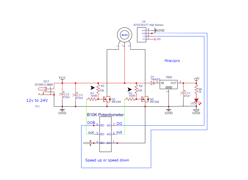
I used the circuit shown below, but I replaced the 100k-ohm resistor with a 10k-ohm one; that is the only major change you need to make.
Everything else has been kept exactly as specified. You can build it exactly like this. Also, make sure there are no gaps between the magnets when placing them; otherwise, it will not self-start.
Ensure there is no space between the magnets—do not leave any empty gaps between the north and south poles. If a gap remains, the motor will not start on its own, and you will have to spin it by hand.
Mane fan ko single wire say wind kiya or2 sensor pryog Kiya 3144 sensor fan ke high speed thi esmay30*20*6 KAY14MAGNATE PERYOG KIYA