CNC Servo Motor up and Down M03 S50 || M05 S50 NOT WORKING PROBLEM SOLVED
To solve GRBL servo motor up and down problems, you must first confirm that standard GRBL does not support RC servo motors (like the SG90) for the Z-axis by default. You need a modified version of GRBL and specific G-code commands. [1, 2, 3, 4]
1. Update Firmware to a Servo-Compatible Version [5]
Standard GRBL sends step/direction signals meant for stepper motors, not the PWM signal a hobby servo needs. [6]
- Download Modified GRBL: Use a version like Grbl_Pen_Servo or MIGRBL.
- Configuration: These versions often treat Z-axis movements above 0 ($Z > 0$) as “Pen Up” and ($Z < 0$)as “Pen Down”. [3, 7, 8, 9, 10]

OR
PEN up = Z0
PEN DOWN = Z0.2
2. Correct Wiring
Connecting a servo to a standard stepper pin will not work. [11]
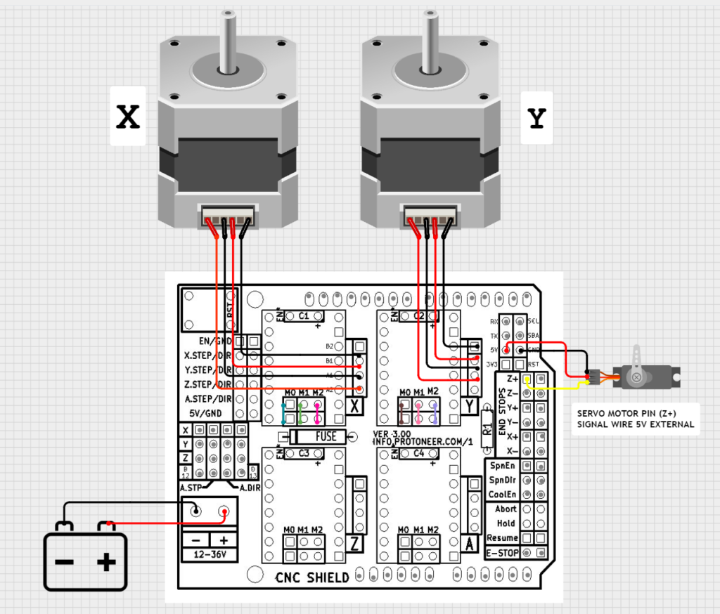
- Signal Pin: Most modified GRBL versions use Pin D11 (Digital 11) for the servo PWM signal. On many CNC shields, this corresponds to the Z+ limit switch pin.
- Power Supply: Do not power the servo from the Arduino’s 5V pin, as it can cause resets. Use a dedicated 5V external power supply and ensure you connect the Ground (GND) of that supply to the Arduino’s Ground. [3, 12, 13, 14, 15, 16]
3. G-Code Commands for Control
If your firmware uses the spindle PWM to control the servo, you use M3 (Spindle On) and M5 (Spindle Off) commands. [1, 13]
- Pen Down:
M3 S###(e.g.,M3 S90orM3 S255). - Pen Up:
M5or a different S-value likeM3 S0. - Delay: Since servos take time to move, add a dwell command like
G4 P0.5(0.5-second delay) after up/down commands. [7, 14, 17, 18, 19, 20]
4. Important GRBL Settings
Check these settings in your G-code sender (like Universal Gcode Sender): [21]
- $30 (Max Spindle Speed): Set this to match your max servo angle/PWM value (e.g., 255 or 1000).
- $31 (Min Spindle Speed): Usually set to 0.
- $32 (Laser Mode): Ensure this is disabled (
$32=0) for the servo functionality to operate. [14, 18, 22, 23, 24]
Summary Troubleshooting Table
| Problem [1, 2, 3, 12, 15, 16, 25] | Likely Cause | Solution |
|---|---|---|
| No movement | Wrong Firmware | Upload a “Servo-fork” version of GRBL. |
| Humming/Buzzing | Stall or Binding | Ensure the servo arm isn’t physically blocked at its limits. |
| Arduino Resets | Power Draw | Use an external 5V power supply for the servo. |
| Reverse Movement | Logic Inverted | Swap the M3 and M5 commands in your CAM software or rotate the servo arm 90°. |
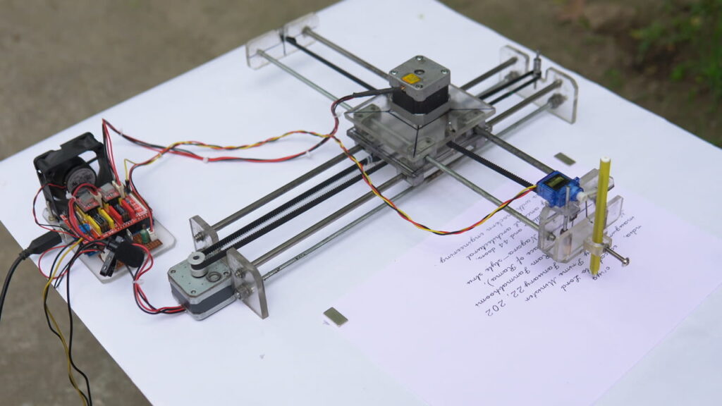
Building a DIY CNC handwriting machine, often called a “homework machine,” involves combining precise mechanical parts with an Arduino-based brain and specialized software to replicate human writing. [1, 2]
1. Hardware & Components
To build a functional writing machine, you will need both mechanical and electronic parts: [3, 4]
- Controller: Arduino Uno or Nano.
- Expansion Board: CNC Shield V3 to connect drivers to the Arduino.
- Motor Drivers: 2x A4988 or DRV8825 stepper drivers.
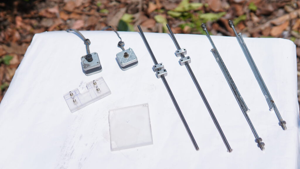
- Motors: 2x Nema 17 Stepper Motors (X and Y axes) and 1x MG90S Micro Servo (Z-axis/pen lift).
- Frame Materials: 2020/2040 V-Slot Aluminum Profiles, 8mm smooth rods, or even recycled DVD drive rails for a mini version.
- Motion Parts: GT2 Timing belts, pulleys, and linear bearings (6mm or 8mm).
- Power: 12V 2A–5A DC Power Adapter. [3, 4, 5, 6, 7, 8, 9, 10]
2. Mechanical Construction
The machine typically follows a Cartesian (X-Y) or CoreXY layout: [11, 12]
- Assemble the Base (Y-Axis): Mount the long aluminum profiles and attach the motor and idler pulleys at opposite ends.
- Build the Gantry (X-Axis): Construct a carriage that slides along the Y-axis. The X-axis motor moves a secondary carriage left and right across this gantry.
- Construct the Pen Holder (Z-Axis): This is a small sliding mechanism with a spring that keeps the pen lifted. The servo motor presses down on the mechanism to lower the pen onto the paper.
- Tensioning: Tighten the GT2 belts using cable ties or tensioning screws to ensure smooth, accurate motion. [3, 4, 7, 9, 13]

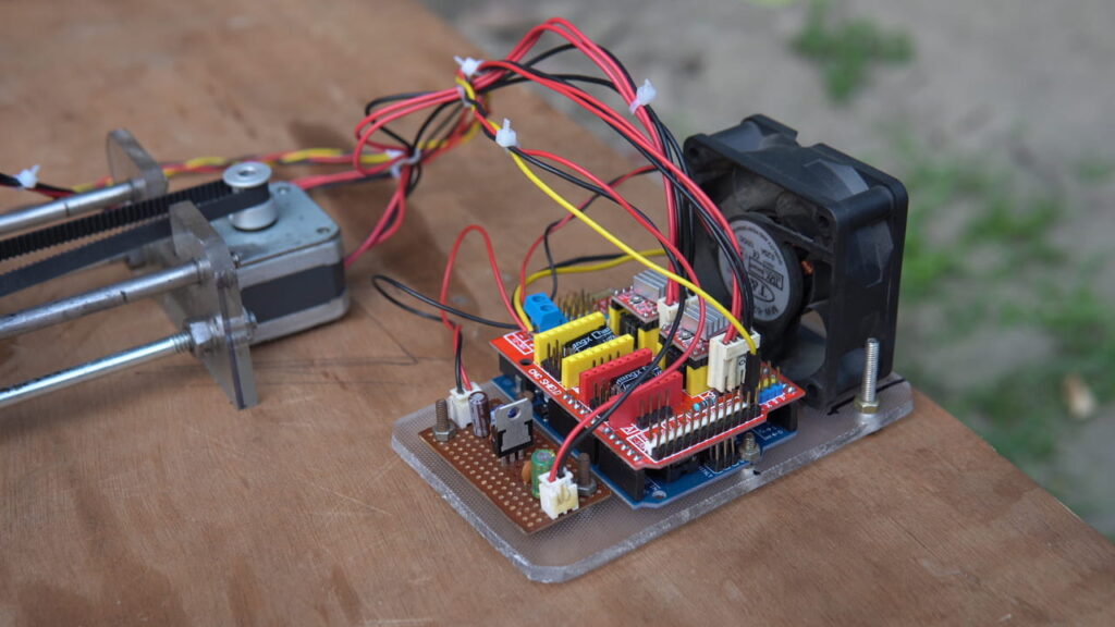
3. Electronics & Wiring
- Mounting: Place the A4988 drivers onto the CNC Shield.
- Connections: Plug the X and Y stepper motors into their respective slots. Connect the servo motor to the “Z+” or specific servo pins on the shield (this often requires a modified firmware pinout).
- Current Adjustment: Use a screwdriver to adjust the small potentiometer on the drivers to prevent motor overheating or skipping steps. [4, 9, 10, 11, 14]
4. Software & Handwriting Replication
To convert your handwriting into machine movements, follow this workflow: [15, 16, 17]
- Firmware: Flash a modified version of GRBL (like GRBL-Servo) to the Arduino. This allows the machine to interpret G-code and use a servo for the pen lift.
- Design & Font:
- Option A (Custom Handwriting): Scan your handwriting, use Inkscape to “Trace Bitmap” into a vector path, and save it as an SVG.
- Option B (Single-Line Fonts): Standard fonts have outlines, which make the machine draw two lines for every stroke. Use “Single Line” or Hershey fonts in Inkscape for natural-looking writing.
- G-Code Generation: Use the Gcodetools extension or MI Inkscape Extension to convert your vector paths into .nc or .gcode files.
- Sender Software: Use Universal G-Code Sender (UGS) or GRBL-Plotter to send the final code to your machine via USB. [3, 9, 11, 18, 19, 20, 21, 22]
5. Calibration
Before writing, you must calibrate the “Steps per mm” in the UGS console: [3, 9]
- Command the machine to move 100mm.
- Measure the actual distance traveled.
- Adjust the $100 (X) and $101 (Y) values until the movement is perfectly accurate. [3, 9, 23]
Do you need help finding 3D printable files for the pen holder or a specific wiring diagram for your shield version?
Creating a CNC writing machine (often called a “homework machine” or 2D plotter) is a popular project that uses an Arduino, stepper motors, and a servo to replicate handwriting or drawings. [1, 2]
1. Essential Materials
To build a functional machine, you will need the following hardware components:
- Controller: Arduino Uno or Nano.
- Motors: 2x Nema 17 Stepper Motors for X and Y axes; 1x MG90S Servo Motor for the Z-axis (pen lift).
- Drivers: CNC Shield V3 and A4988 or DRV8825 stepper drivers.
- Frame: 20×20 or 20×40 Aluminium V-Slot profiles (or 8mm smooth rods with bearings).
- Motion: GT2 Timing belts and pulleys.
- Power: 12V 2A Power Adapter. [1, 2, 3, 4]
2. Mechanical Construction
The machine typically uses a Cartesian (X-Y) coordinate system. [5, 6]
- X-Axis: Build a gantry that moves left and right using one stepper motor and a belt.
- Y-Axis: Construct a base or sliding rail that moves the entire X-axis gantry forward and backward.
- Z-Axis (Pen Holder): Use a small sliding mechanism (3D printed or acrylic) with a spring. The servo motor pushes the pen down to write and lets the spring pull it back up.
- Assembly: Ensure all rails are smooth and the belts are tight to prevent “ghosting” or shaky handwriting. [1, 2, 7, 8, 9]
3. Software Setup
The “brain” of the machine requires firmware to translate computer commands into motor movements. [10]
- Firmware: Flash GRBL to your Arduino. Note: You often need a modified version of GRBL that supports Servo motors for the Z-axis.
- Design Software: Use Inkscape (free) to create text or drawings. You must convert your design into a “Path” so the machine can follow the lines.
- G-Code Extension: Install an extension in Inkscape (like MI GRBL or Gcodetools) to export your design as G-Code (the language CNCs speak).
- Sender: Use Universal G-Code Sender (UGS) to connect your PC to the Arduino and stream the G-Code file to the machine. [1, 11, 12, 13, 14]
4. Replicating Your Own Handwriting
To make the machine write in your specific hand:
- Scan your writing: Write a character set (A-Z, 0-9) on paper and scan it into your computer.
- Vectorize: Use Inkscape to trace the bitmap image of your writing into vector paths.
- Font creation: Save these as individual SVG/DXF files or use a tool to create a custom plotter-friendly font. [15, 16]
Would you like a more detailed wiring diagram for the Arduino and CNC shield, or should we look at specific 3D print files for the frame?
DOWNLOAD LINK:
ARDUINO SOFTWARE
GRBL CODE
Grbl Servo Master
Inkscape 0.92.5
4xiDraw & Km Laser
G Code Sender Download (UGS)
20 Minute I MAKE the Top Best Homework Writing CNC Machine Vary in High Performance || QUALITY GOOD
CNC Servo Motor up and Down CODE GRBL PROBLEM SOLVE M03 M05 NOT WORKING
The reason your servo responds to Z axis commands but not M03/M05 is that standard GRBL firmware treats the Z-axis as a stepper motor, while M03/M05 are simple on/off signals for a spindle motor. To solve this and use M03/M05 properly, you must upload a modified GRBL library specifically designed for servos, such as MIGRBL or grbl-servo. These versions repurpose the Spindle PWM (Pin 11 / Z+) to send the correct pulse signals required by hobby servos. Once the correct firmware is flashed, you can use M03 S90 for “Pen Up” and M03 S10 or M05 for “Pen Down,” adjusting the S value to set the exact angle. If you prefer to keep using Z commands because they are already working, ensure your G-code generator is set to “3-axis” mode; however, switching to the servo-modified firmware is the best long-term fix for proper pen plotter operation. [1, 2, 3, 4, 5, 6, 7, 8, 9]
Key Steps to Fix M03/M05:
Flash Correct Firmware: Download a servo-enabled GRBL version. You must delete the old “grbl” folder from your Arduino libraries directory before installing the new one to avoid conflicts.
Connect to PWM Pin: Attach your servo signal wire to the Z+ (Pin 11) header on your CNC shield.
External Power: Power the servo with an external 5V supply rather than the Arduino’s 5V pin to prevent voltage drops that can reset your board.
Check GRBL Settings: Send $$ in your serial console and verify that $30 (Maximum Spindle Speed) is set to 255 or 1000 so that the S command has a range to move the servo. [4, 5, 6, 7, 10, 11, 12]
Would you like the exact G-code commands to test your servo’s “up” and “down” angles manually?
alternative (Z0 pen up) (Z0.2 pen down )
If as a student of ece I want to buy this from you what price would you give it to me ? The homework machine
I am planning to build a CNC machine for sale. Therefore, please wait a little longer; I have a new project coming very soon—an exceptionally high-quality CNC machine that will operate with remarkable efficiency, flawless precision, and aesthetic elegance. I am currently busy with its construction. If you are interested, you will be able to acquire this unit; moreover, it will be available at a very affordable price.
Sir if I will buy it so how much price?
Are you talking about buying *this* specific item of mine, or are you referring to a product from the company?
hola muchas gracias exelente maquina , me gusto mucho y quiero hacer una pero no tengo claro el modulo que va del servo motor a la placa de arduino , no veo la construccion de ese modulo o el esquema
Thank you so much for reading my post and watching my video, and for checking out my project. I hope you are doing well.
Yes, I understand what you mean. Actually, I didn’t build a separate board for the Arduino and the servo motor; the circuit I created here is just a 5-volt section. The reason is that if I draw 5 volts from the Arduino to power the servo motor, the Arduino resets whenever the servo motor takes on a load. So, I built a separate 5-volt circuit using a 7805 IC to run the servo motor, while the main signal still comes from the CNC shield. If you look closely, I’ve shown exactly where the signals go—make sure to watch the full video.