Using four diodes in a bridge circuit, a bridge rectifier converts alternating current (AC) into direct current (DC). Electrical current can only flow in one direction through a diode. In a bridge circuit, only two of the four diodes are electrically active when an AC input is provided.
Components of a Bridge Rectifier Circuit
Diodes are semiconductors that allow current to flow in one direction while blocking it in the opposite. A bridge rectifier circuit consists of four diodes stacked in a bridge arrangement. These diodes could be standard silicon diodes or more powerful Schottky diodes, depending on the specific application.
Transformer
The transformer is a crucial component in the bridge rectifier circuit. It lowers the high-voltage AC input from the main supply to a lower voltage that is suitable for rectification. The transformer creates a barrier between the AC input voltage and the rectified DC output.
Filter Capacitor
The filter capacitor is used to smooth the rectified DC output by reducing ripple voltage. By holding electrical charge at periods of peak voltage and releasing it during lower voltage periods, it creates a more steady DC output.
The Following Diagram shows How a bridge rectifier works:
The AC input can be seen at Terminals A and B. The DC output is produced by the load resistor R L, which is connected between terminals C and D. The load resistor is the component that uses DC power.
When the AC input is positive at terminal A and negative at terminal B, diodes D 1 and D 3 are forward biased and conduct current while diodes D 2 and D 4 are reverse biased and do not. From A to C, the current flows through D1 and RL, and from D to B, through D3. The output voltage across R L is positive at C and D.
When the AC input is negative at terminal A and positive at terminal B, diodes D 1 and D 3 are reverse biased and do not conduct current, whereas the forward biased diodes D 2 and D 4 do. From B to C, the current travels via D4 and RL, while from D to A, it travels via D2. The output voltage across R and L is still positive at C and D.
As a result, the output voltage across R L always has the same polarity regardless of the polarity of the AC input. To put it another way, the bridge rectifier converts AC to DC.
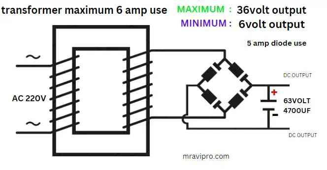
Bridge Rectifier Circuit Diagram
The diagram for the bridge rectifier circuit indicates where the filter capacitor, transformer, and diode should be placed. Below is a diagram of a bridge rectifier circuit:
How Does a Bridge Rectifier Circuit Work?
When an AC voltage is provided, the diodes in the bridge rectifier circuit control the current flow. Let’s follow a step-by-step procedure to comprehend the workings of the bridge rectifier circuit:
- The diodes D1 and D2 become forward-biased during the positive half-cycle of the AC input, allowing current to flow through them. The current flow is simultaneously obstructed by the reverse-biased diodes D3 and D4.
- The secondary winding of the transformer and the diodes D1 and D2 both experience current flow as a result of this forward-biased state. The load linked to the bridge rectifier circuit is next to receive the current.
- Positive half-cycles bias diodes D1 and D2, whereas negative half-cycles of the AC input bias diodes D3 and D4. As a result, current passes through D3, D4, the secondary winding of the transformer, and the load.
- These alternating currents work together to flow through the load, producing a rectified output voltage. By lowering the ripple, the filter capacitor further smoothes this set voltage.
12v 7ah Circuit Diagram Download Free
Advantages of Bridge Rectifier Circuit
Compared to alternative rectification strategies, the bridge rectifier circuit has a number of benefits. Among the main advantages are:
- Full-Wave Rectification: The bridge rectifier circuit, which makes use of both halves of the input AC cycle, offers full-wave rectification as opposed to half-wave rectification.
- Higher Efficiency: Due to its capacity to rectify complete waves, the bridge rectifier circuit has a higher efficiency than conventional rectifiers.
- Compact Size: The bridge rectifier circuit is compact and economical because of its straightforward configuration, which allows for the implementation of the circuit with a minimal amount of components.
- Lower Ripple: Compared to unfiltered rectifiers, the bridge rectifier circuit with a filter capacitor generates a smoother DC output with substantially less ripple.
Applications of Bridge Rectifier Circuit
Many different electronic systems and devices employ the bridge rectifier circuit. Typical applications examples include:
- Power Supplies: In power supply units, bridge rectifier circuits are frequently used to transform AC mains voltage to DC voltage for powering electronic devices.
- Battery Charging: By converting AC voltage from a charger into DC voltage suited for battery charging, bridge rectifiers play a crucial part in the charging of batteries.
- LED Lighting: Bridge rectifier circuits are commonly used in LED lighting systems to change the AC input to the DC voltage needed for the LEDs to operate efficiently.
- Motor Drives: Bridge rectifiers are used in motor control circuits to transform the AC power source into the proper DC voltage for motor operation.
Also, Read This Article
- Also, Read This Article:- 12V 7Ah Battery Charger Circuit Diagram
- Also, Read This Article:- 3.7Volt Li-ion Battery Charger Full Details & solution.
- Also, Read This Article:- How to Make a BLDC Motor ESC Using MOSFET
- Also, Read This Article:– 555 timer ic use throttle or accelerator sensor circuit diagram
- Also, Read This Article:- How to Make a BLDC Motor ESC Using MOSFET
- Also, Read This Article:- 5V PWM Signal Booster Convert 12V PWM Signal Generator
- Also, Read This Article:- How to Make a BLDC Motor ESC Using MOSFET
- Also, Read This Article:- RU6888r Mosfet Datasheet Full Details Download Free
Conclusion
In conclusion, a bridge rectifier circuit is an essential component of electronic circuits because it makes it possible to convert AC voltage to DC voltage. Understanding their circuit construction, operating principle, advantages, and applications can help you successfully use bridge rectifier circuits in your electronic projects. Always be cautious and prioritize safety when working with high-voltage circuits.
FAQ
What is the purpose of a bridge rectifier circuit?
The primary purpose of a bridge rectifier circuit is to convert alternating current (AC) into direct current (DC) for various electronic applications.
How does a bridge rectifier differ from a half-wave rectifier?
In contrast to a half-wave rectifier, which utilizes just one half of the AC cycle, the bridge rectifier circuit utilizes both halves of the cycle, resulting in more efficient full-wave rectification.
Can I use different diodes in a bridge rectifier circuit?
Indeed, you can use a variety of diode types based on your particular requirements. Schottky and conventional silicon diodes are often used in bridge rectifier systems.
Is a filter capacitor necessary in a bridge rectifier circuit?
Bridge rectifier circuits typically include a filter capacitor, though it is not necessarily necessary, to reduce ripple voltage and produce a more consistent DC output.
Can I parallel multiple bridge rectifier circuits for higher current requirements?
It is feasible to parallel many bridge rectifier circuits to increase the current-carrying capacity for higher current applications.
What safety precautions should I follow when working with a bridge rectifier circuit?
When working with a bridge rectifier circuit, it is essential to take the proper electrical safety precautions, which include isolating the circuit, avoiding direct contact with high voltage, and donning the necessary protection gear.